Category: Technical Guides

  • RTO Condensate Drain Inspection: Prevent Hidden Air Paths and Liquid Accumulation

    RTO Condensate Drain Inspection: Prevent Hidden Air Paths and Liquid Accumulation

    RTO Condensate Drain Inspection: Prevent Hidden Air Paths and Liquid Accumulation

    Condensate drains are easy to overlook because they sit below the main exhaust path. Yet a blocked low point can retain liquid, while an open, dry, damaged, or incorrectly routed drain can become an unintended air path. Either condition may complicate pressure balance, corrosion review, startup, and troubleshooting.
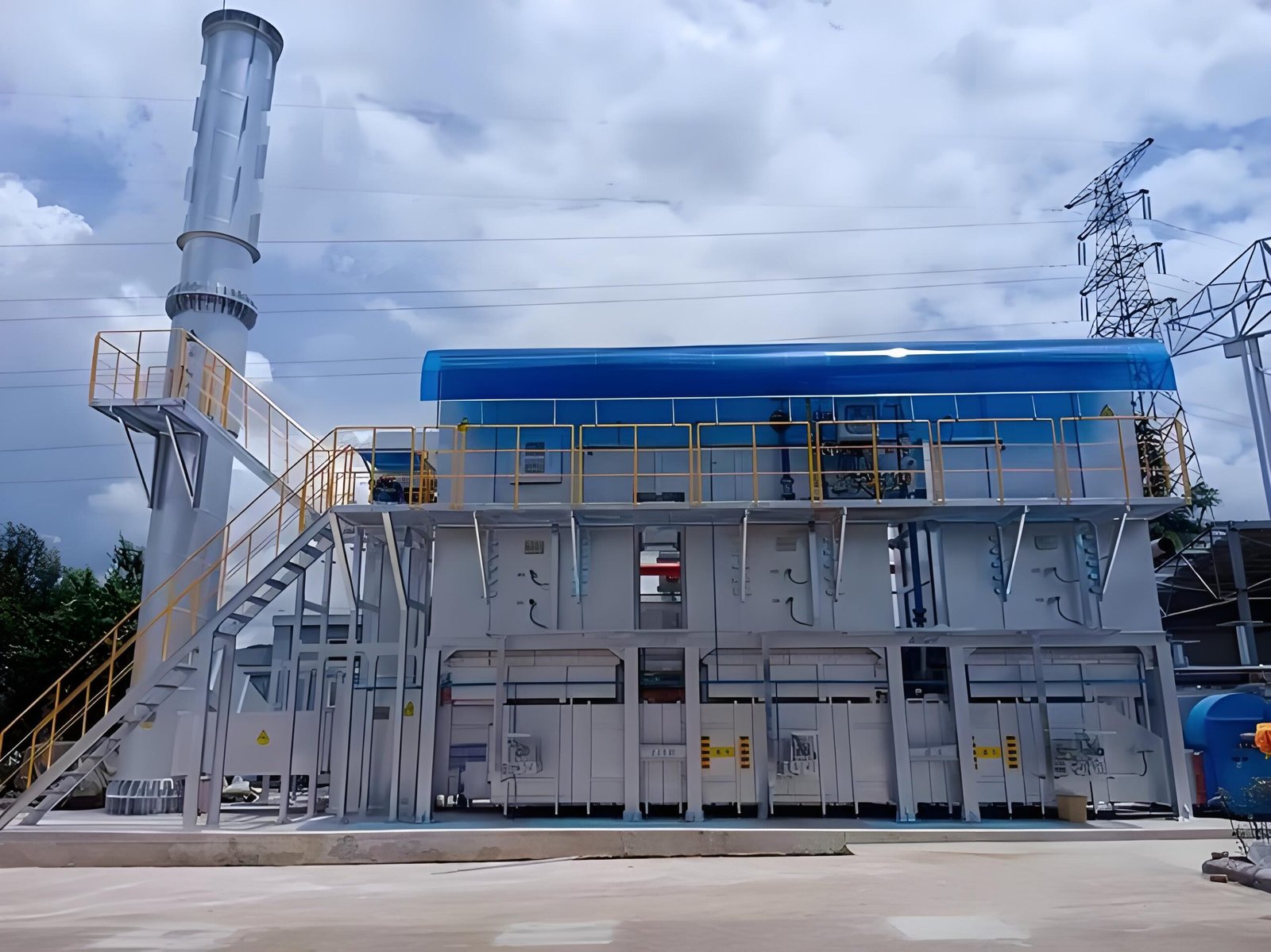
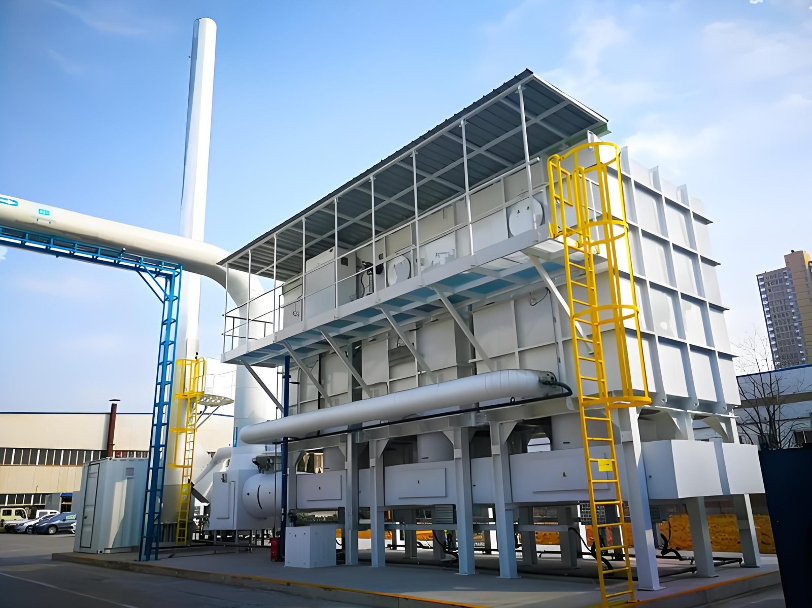
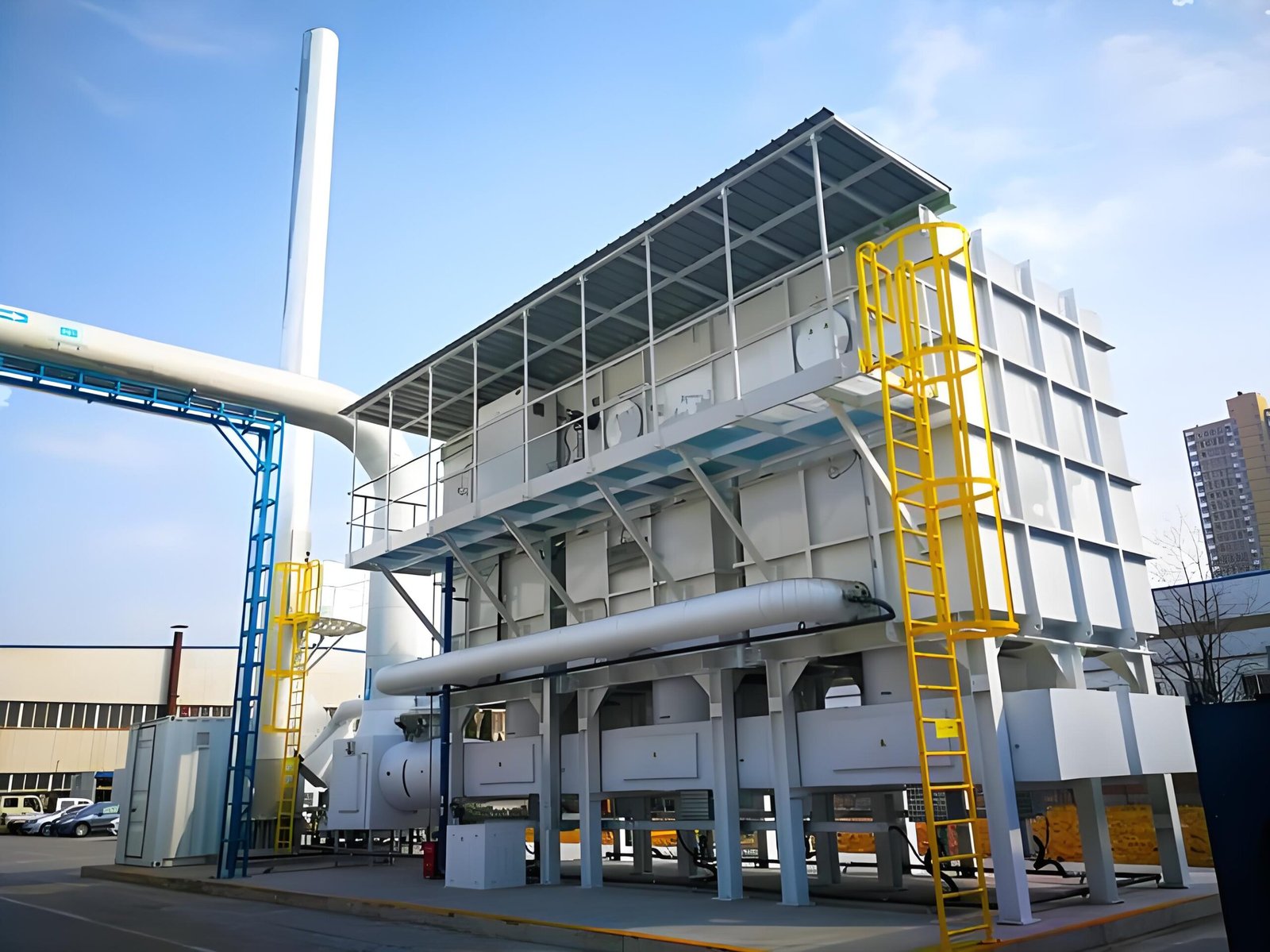
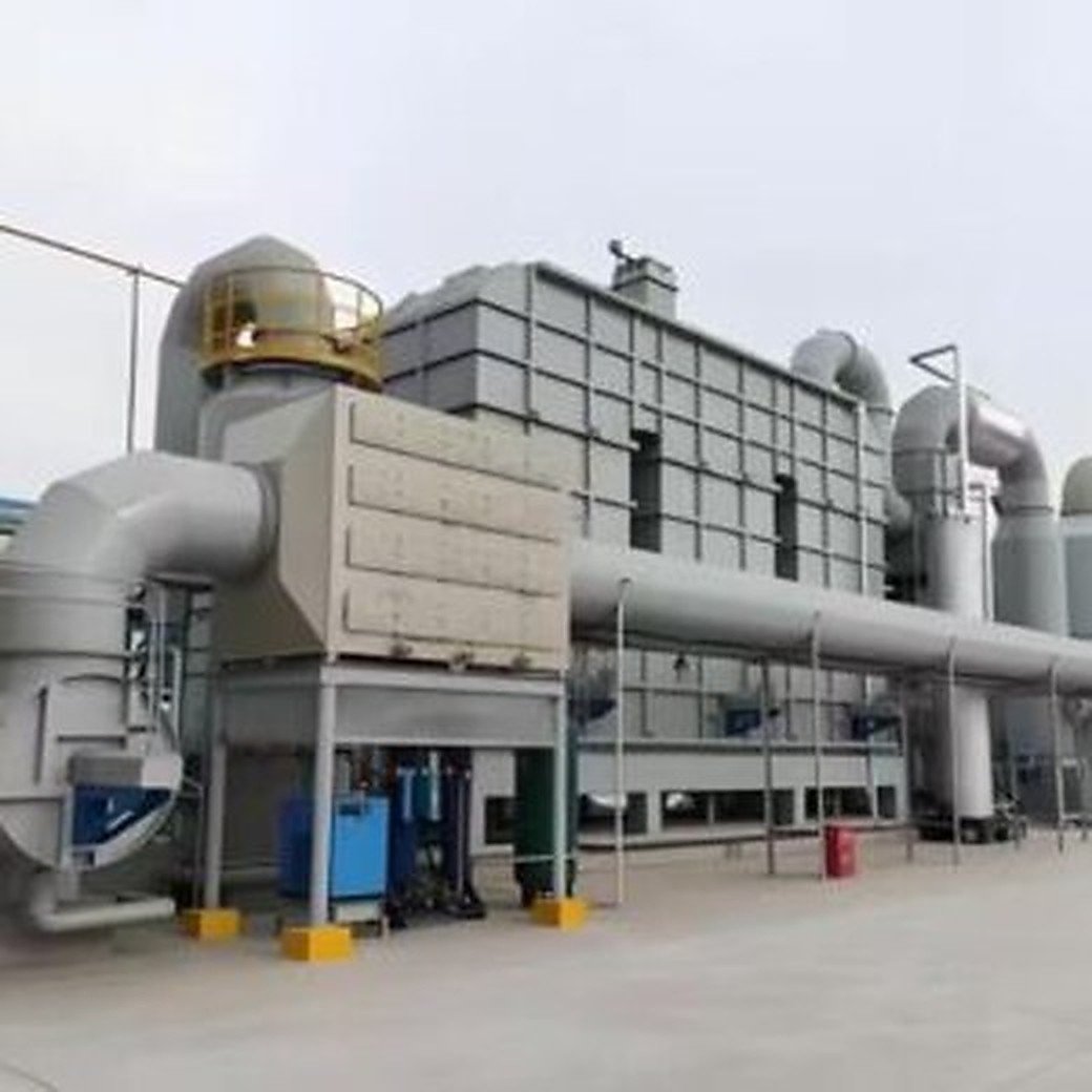
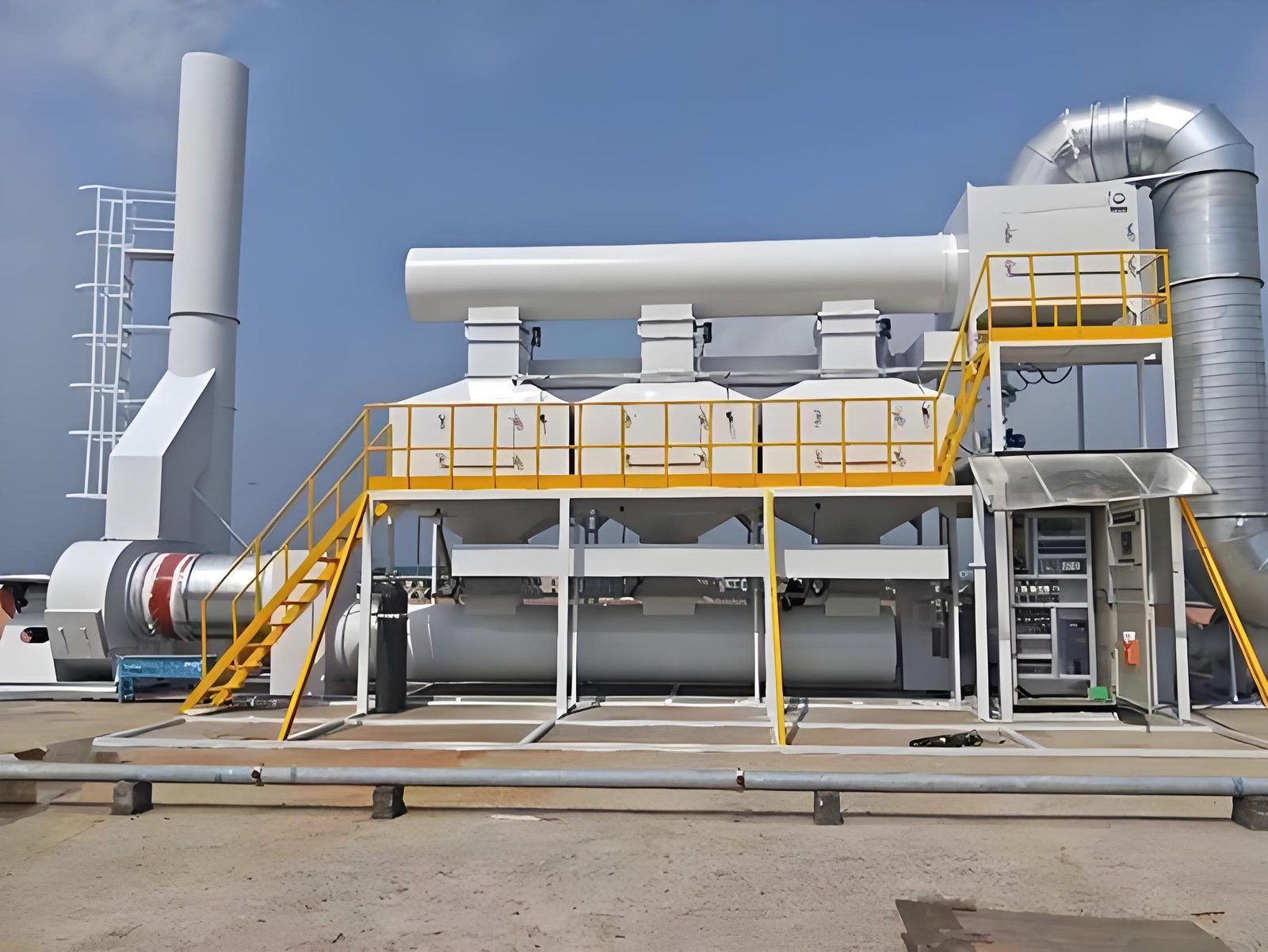
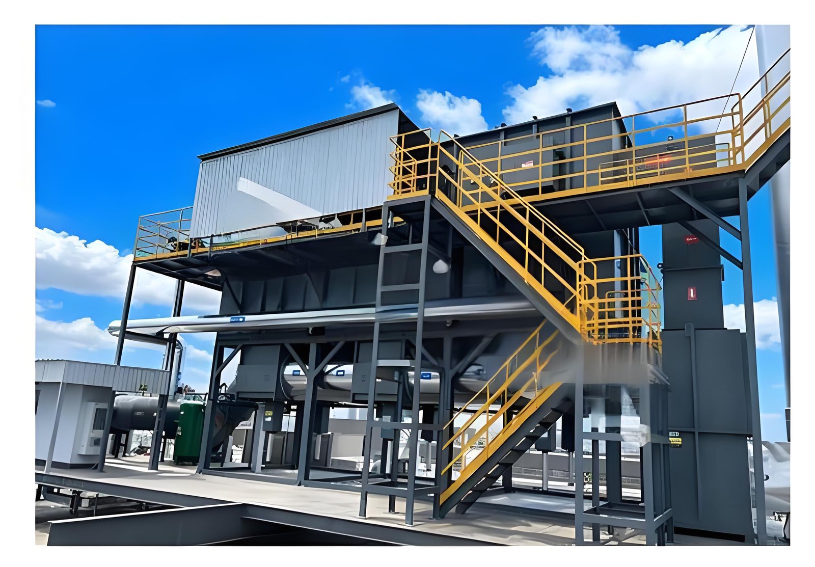
    Industrial RTO system and lower equipment boundary during a drain inspection review

    The correct question is not simply whether liquid comes out of a valve. Plant teams need to understand where liquid can form, how each drain maintains the gas boundary, what operating state was observed, and what evidence is required before return to service.

    1. Map every low point and drain boundary

    Start with current drawings and a field walkdown. Mark duct low points, knock-out sections, drain pots, traps, manual and automatic valves, hoses, heat tracing, insulation, discharge destinations, and nearby pressure connections. Confirm which sections operate under negative or positive pressure in startup, production, bypass, purge, and shutdown modes.

    Do not assume that a drain shown on an old drawing still has the same routing. Record field differences for controlled review.

    2. Identify credible liquid sources

    Liquid may come from process carryover, condensation during cold startup, weather ingress, washdown, leaking coils, or an upstream separator upset. Document the production case, exhaust temperature, recent shutdown history, ambient conditions, and upstream changes. Avoid assigning the liquid to one source without evidence.

    3. Inspect without opening an uncontrolled gas path

    Follow site isolation, lockout, cooling, gas-testing, and PPE requirements. Check for corrosion, plugged tubing, damaged valves, missing caps, failed seals, frozen or inactive heat tracing, sagging hoses, unsupported piping, and discharge lines that rise after leaving the low point.

    A drain should not be opened on a live boundary merely to prove flow. The safe verification method depends on the installed design and site procedure.

    4. Separate blockage clues from false-air clues

    ObservationPossible explanationsEvidence to collect
    Liquid remains at a low pointPlugging, poor slope, closed valve, failed tracing, or excess carryoverLevel evidence, line condition, tracing status, operating history
    Pressure changes near a drainDry trap, open valve, damaged seal, instrument drift, or another duct leakValve position, trap condition, pressure checks, comparable operating case
    Corrosion around a drainCondensation, chemical carryover, external water, or insulation damageLiquid characterization, photos, material records, insulation inspection
    Repeated freezingInadequate tracing, insulation damage, power loss, or unsuitable routingCircuit status, ambient history, routing and insulation review

    5. Define an RFQ-ready corrective scope

    A useful work scope identifies the drain tag, drawing revision, pressure and temperature basis, materials, isolation assumptions, access, disposal boundary, tracing and insulation interfaces, inspection hold points, and required as-left records. State whether the supplier must clean, repair, reroute, replace, or only inspect each component.

    6. Establish restart release evidence

    Before restart, confirm valve lineup, caps and plugs, trap fill or seal condition where applicable, tracing availability, insulation closure, discharge routing, and removal of temporary hoses or blanks. Record photographs and responsible sign-off. During controlled startup, watch pressure, temperature, fan load, drain condition, and any recurrence of liquid.

    7. Build a repeatable inspection record

    Keep the tag, location, operating state, observed liquid, valve position, tracing status, photographs, deviations, and action owner in one searchable record. Trend evidence is more useful than an isolated statement that a drain was “checked.”

    Buyer checklist

    • Are all low points and drains shown on current drawings?
    • What maintains the gas seal in each operating mode?
    • Who owns isolation, cleaning, waste handling, tracing, and insulation?
    • Which measurements must be confirmed before fabrication?
    • What inspection and restart records are included in the supplier scope?

    FAQ

    Can an open RTO drain affect system pressure?

    It can if the drain communicates with a negative- or positive-pressure gas path, but the effect depends on the installed arrangement. Verify the boundary rather than assuming a universal result.

    Does liquid at a drain prove process carryover?

    No. Condensation, weather, washdown, and other sources must also be considered.

    Should every drain have heat tracing?

    Not universally. The decision depends on climate, liquid properties, routing, operating states, and the approved design basis.

    What should be checked after drain work?

    Confirm mechanical closure, valve lineup, seal condition, routing, tracing and insulation, then observe the controlled restart using defined pressure and temperature indicators.

    Professional CTA

    If your RTO has recurring liquid accumulation, frozen drains, corrosion at low points, or an unexplained pressure change, send SERNO the current duct layout, drain photographs, operating states, and recent maintenance history. We can help organize the evidence and define a technically comparable inspection or repair scope.
  • RTO Expansion Joint Inspection: Build a Repair Scope Before False Air Becomes a Reliability Problem

    RTO Expansion Joint Inspection: Build a Repair Scope Before False Air Becomes a Reliability Problem

    RTO Expansion Joint Inspection: Build a Repair Scope Before False Air Becomes a Reliability Problem

    Expansion joints are small-looking components on a large exhaust system, but they sit at a difficult boundary: hot ductwork moves, supports carry load, insulation hides condition, and the joint must accommodate movement without becoming an unintended opening. A torn cover, displaced liner, loose flange, failed clamp, or overloaded support can allow air in or process gas out. The same observation can also be confused with a damper problem, fan-pressure change, sampling issue, or normal thermal movement.

    For an RTO owner, the useful question is not “Does this joint look old?” It is: what evidence shows that the joint is outside its intended service condition, what risk does that create, and what repair boundary can a contractor quote and verify? This guide gives a field-review sequence. It does not replace the joint manufacturer’s design data, a site isolation procedure, or a local emissions and safety assessment.

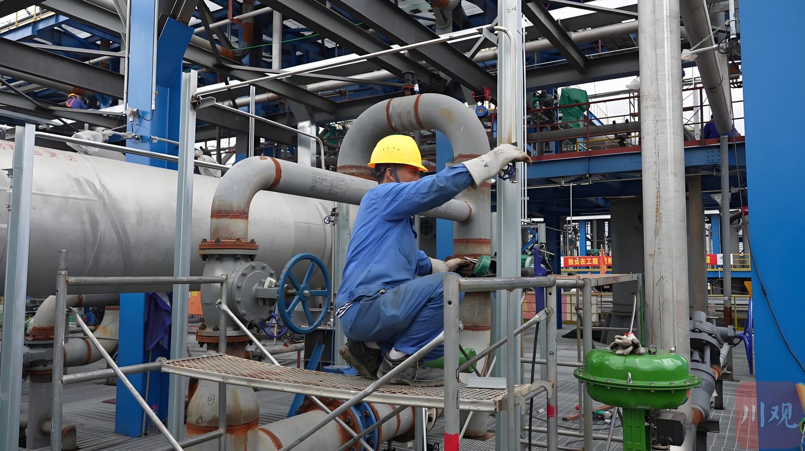
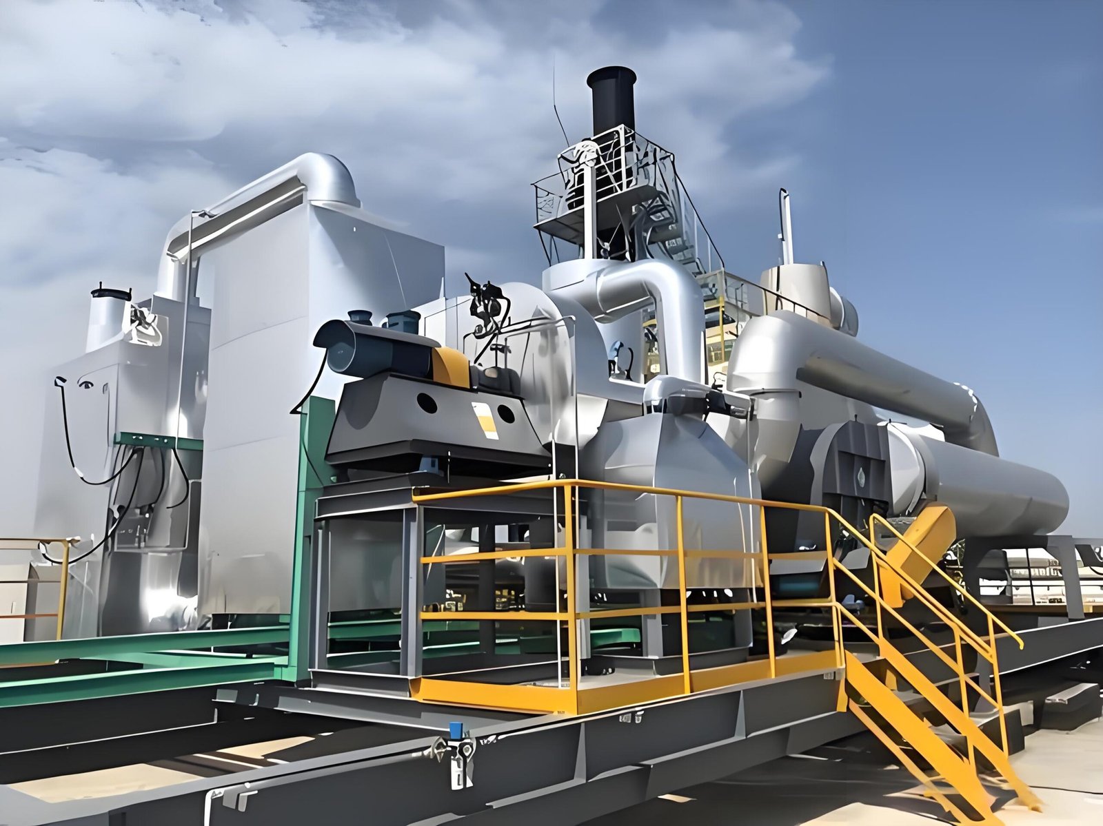
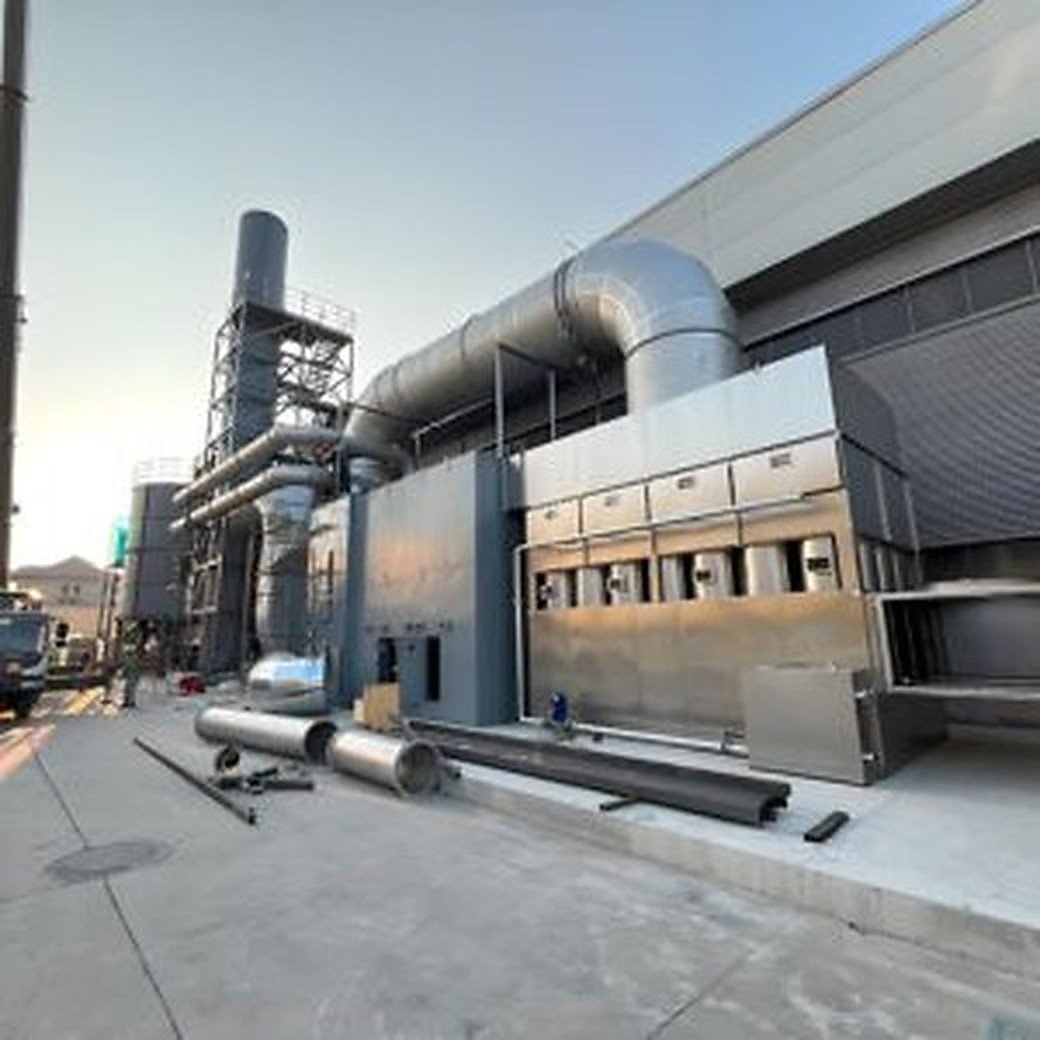
    RTO exhaust duct and expansion-joint area for field inspection

    1. Start with the movement and gas-path map

    Before opening insulation or planning a replacement, mark every flexible connection on the current as-built drawing. Record whether the joint is on the hot-gas path, combustion-air path, purge path, bypass, or a utility connection. Note nearby fans, dampers, supports, guides, anchors, drains, access doors, insulation breaks, and sample points.

    The map should answer four practical questions:

    • Which components can move relative to each other during heat-up and cooldown?
    • Which side is expected to see negative or positive pressure in each operating mode?
    • Can a joint be isolated and inspected without opening the process boundary elsewhere?
    • What downstream instrument or observation would change if air entered at this point?

    Do not infer the pressure direction from a generic RTO diagram. Confirm it from the installed fan arrangement, operating sequence, and approved drawings.

    2. Inspect the joint without turning a clue into a conclusion

    Use the site’s permit, lockout, cool-down, and access controls first. A visual inspection can document condition without proving a leak. Photograph the joint from a repeatable angle and include a reference to the equipment tag or drawing grid, not a customer name or sensitive identifier.

    Look for:

    • cuts, pinholes, fraying, hardening, blistering, or heat discoloration on the cover;
    • a displaced inner liner, exposed insulation, or a cover pulled off-center;
    • loose, missing, or unevenly tightened fasteners and clamps;
    • flange distortion, witness marks, rubbing, or contact with a support;
    • compressed travel that leaves no movement allowance, or excessive extension;
    • support, guide, or anchor changes that transfer load into the joint;
    • moisture, dust tracks, or deposits that indicate a possible flow path.

    These are condition observations. They become stronger evidence only when connected to the design movement range, temperature history, pressure condition, and a controlled inspection or test.

    3. Compare as-found condition with thermal movement evidence

    An expansion joint can appear to move during normal operation. The review should therefore compare the as-found position at defined operating states: cold, warm-up, stable production, and cooldown where safe and practical. Record the operating state, approximate time, nearby temperature readings, fan or damper state, and any maintenance work completed since the last baseline.

    Avoid using a single photograph as a travel limit. If the joint has travel indicators, witness marks, or manufacturer-specified movement dimensions, record them against the approved drawing. If no reliable baseline exists, state that limitation and define a controlled baseline task rather than inventing an acceptance value.

    4. Separate false-air clues from other RTO causes

    Air ingress may change fan loading, pressure balance, temperature patterns, or apparent fuel demand. It is not the only explanation. A disciplined review compares the joint evidence with process load, airflow, damper position, valve sequence, analyzer quality, and recent maintenance.

    ObservationPossible explanationsEvidence to collect before a repair decision
    Fuel demand rises while inlet VOC load is similarAir ingress, lower heat recovery, changed airflow, sensor drift, or process variationComparable operating case, fuel trend, airflow/pressure data, temperature and calibration records
    Dust or moisture track near a jointLocal leakage, washdown, condensation, insulation damage, or a nearby drain pathDirection of track, joint condition, weather/process history, isolation inspection
    Duct pressure changes after maintenanceJoint or support disturbance, damper position, fan change, filter condition, or instrument errorWork pack, command/feedback trace, fan data, differential-pressure checks
    Cover is frayed but no operating change is provenAging, rubbing, thermal fatigue, or an early leak pathMovement clearance, rub marks, liner condition, OEM repair criteria

    The goal is to preserve alternatives until the evidence supports a narrower conclusion.

    5. Define the repair boundary a supplier can quote

    “Replace the expansion joint” is rarely a complete scope. The purchase package should identify the joint tag, physical limits, drawing revision, dimensions to verify in the field, material and temperature basis from the OEM, access and lifting needs, isolation assumptions, and the disposition of adjacent insulation and supports.

    Ask the supplier to state explicitly:

    1. whether the proposed work is a cover-only repair, liner repair, complete joint replacement, or a wider duct correction;
    2. which measurements are required before fabrication and who owns them;
    3. how adjacent guides, anchors, flanges, gaskets, and fasteners will be checked;
    4. what temporary protection is needed during hot work, lifting, or weather exposure;
    5. what inspection and leak-evidence records will be delivered at handover.

    This keeps a small component from becoming an uncontrolled change to the gas path.

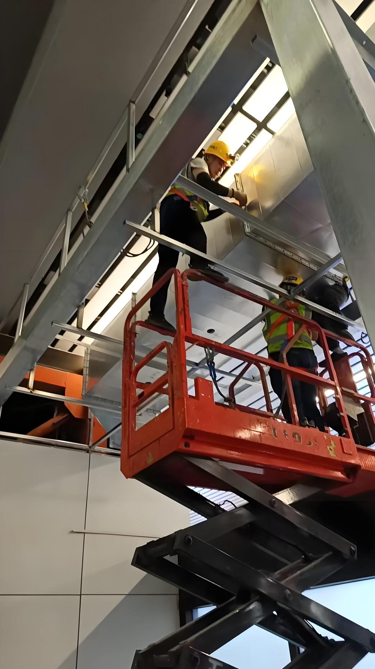
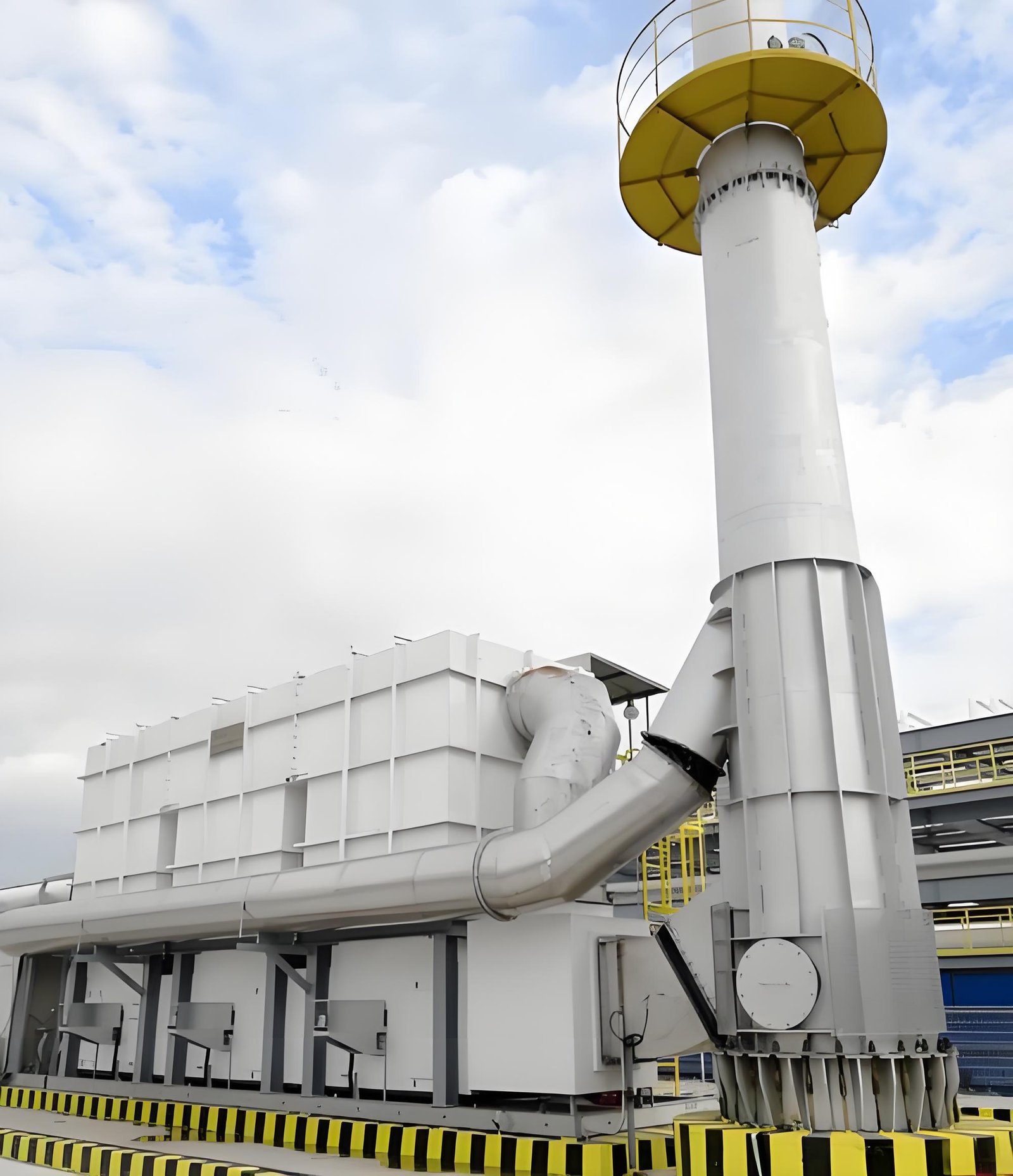
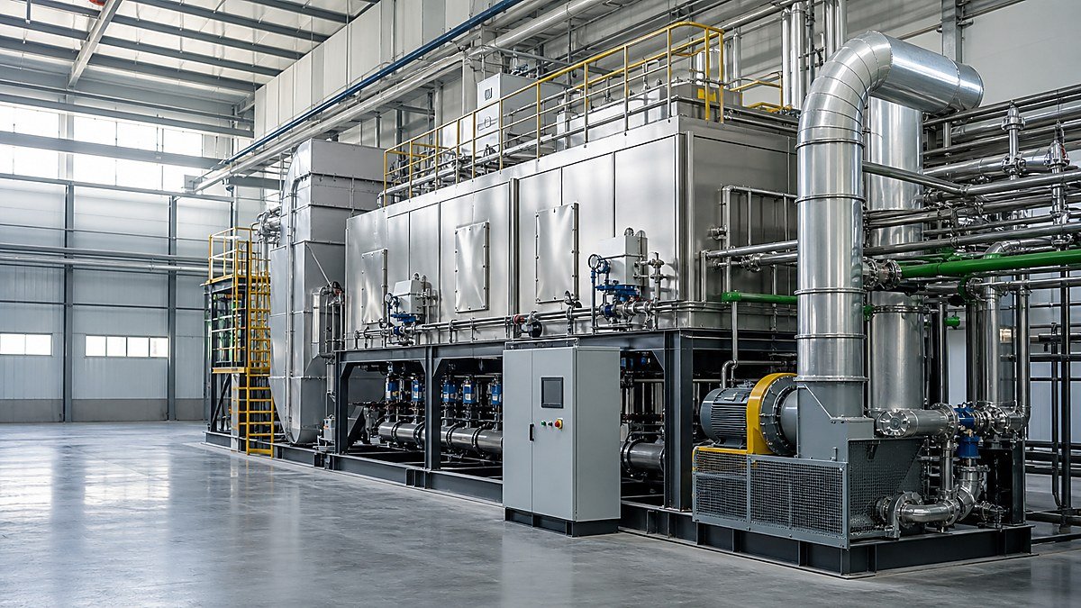
    Maintenance inspection of an insulated RTO duct connection and flexible boundary

    6. Plan isolation, access, and work quality before shutdown

    Expansion-joint work often depends more on access and isolation than on the fabric component itself. Confirm how the RTO will be placed in a safe state, how residual heat and process gas will be managed, and whether the work requires scaffolding, a crane, weather protection, or removal of cladding.

    The work pack should include:

    • isolation points and a positive confirmation method;
    • cool-down, purge, gas-test, and confined-space requirements defined by the site;
    • temporary support or load-transfer controls;
    • protection of nearby sensors, insulation, cables, and coatings;
    • dimensional checks before fabrication and after fit-up;
    • fastener, gasket, liner, and cover inspection records;
    • photographs of as-found, open, installed, and as-left conditions;
    • a controlled return-to-service and observation plan.

    The exact test method depends on the joint design and site procedure. Do not promise a pressure test, smoke test, or emissions result when the installed boundary or local safety rules do not support it.

    7. Build an evidence pack for restart and future diagnosis

    Close the loop with a small, searchable record. Include the tag and drawing reference, operating state, photographs, measured dimensions, material certificates if required by the approved scope, inspection sign-offs, deviations, and the date and person responsible for each observation.

    After return to service, compare the same operating indicators used in the pre-work review. A stable result is useful evidence, but it does not prove that every possible leakage path is eliminated. If a VOC, pressure, temperature, or fuel trend remains abnormal, continue the isolation sequence rather than assigning the cause to the repaired joint by default.

    Buyer checklist: questions before approving the repair

    Review itemMinimum question
    IdentificationIs the joint tag and drawing revision unambiguous?
    Design basisWhat movement, temperature, pressure, and material basis applies to this installed joint?
    ConditionWhich observations are documented as-found, and which are still hypotheses?
    InterfacesAre supports, guides, anchors, insulation, flanges, and nearby instruments inside or outside the scope?
    IsolationWhat safe-state, purge, cool-down, and access steps are required by the site?
    VerificationWhat as-left inspection and controlled restart evidence will be delivered?
    Change controlWill the repair alter duct geometry, support loads, or the approved operating sequence?

    FAQ

    Can a frayed expansion-joint cover prove an RTO emissions problem?

    No. It is a condition clue. Link it to pressure, temperature, operating-state, and inspection evidence before assigning it as the cause of an emissions observation.

    Should every old expansion joint be replaced during an outage?

    Not automatically. Review the installed design, movement history, visible condition, interfaces, and the consequences of opening the boundary. A documented inspection can support a repair, monitoring action, or replacement scope.

    What information should be sent with an RFQ?

    Send the joint tag, current drawings, photographs, dimensions to verify, operating temperature and pressure basis where approved for sharing, access constraints, isolation assumptions, and the inspection records expected at handover.

    Does a repaired joint require a new RTO performance test?

    The answer depends on the site change-control process and what the repair changes. Define the release evidence with the responsible engineering and EHS teams; do not assume a generic test is sufficient.

    Practical CTA

    If an RTO expansion joint is showing wear, dust tracking, movement concerns, or a suspected false-air path, prepare the drawing, photographs, operating states, and recent maintenance record before requesting a repair scope. SERNO can review the boundary with the relevant RTO, duct, fan, and pretreatment context and help define the information needed for a technically comparable quotation.

  • RTO Filter Stock Planning: Set Evidence-Based Change Triggers for High-Dust VOC Exhaust

    RTO Filter Stock Planning: Set Evidence-Based Change Triggers for High-Dust VOC Exhaust

    RTO Filter Stock Planning: Set Evidence-Based Change Triggers for High-Dust VOC Exhaust

    For an RTO inlet train, “keep some spare filters” sounds simple until production is waiting, the installed element has an unclear configuration, and the only available signal is a single differential-pressure reading. In high-dust VOC service, a prefilter is part of the boundary that protects fans, ductwork, downstream heat-transfer surfaces, and—where installed—a concentrator or catalytic stage. A stock decision therefore needs more than a warehouse count.

    The useful question is not how many filters should every plant hold? It is: what evidence tells this plant when stock is at risk, which replacement is actually suitable, and who can make a controlled change decision? The answer depends on the exhaust source, loading pattern, element construction, storage condition, approved change procedure, supplier information, and the plant’s own risk review. This guide offers a decision structure, not a universal service-life or differential-pressure limit.

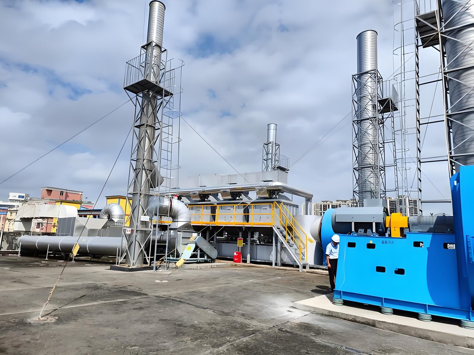
    Industrial RTO inlet ductwork and fan installation for high-dust VOC filter stock planning

    1. Define the protected boundary before counting inventory

    Start by mapping the part of the exhaust path that the filters protect. The boundary may include capture duct branches, a pre-separator, the filter housing and its access doors, pressure taps, the induced-draft fan, isolation or bypass dampers, and the RTO inlet. If an RTO uses a zeolite rotor or an RCO catalyst downstream, the contamination sensitivity may change what the team needs to record.

    This map prevents an inventory error: treating every similar-looking cartridge or panel as interchangeable. A spare may be physically close in size yet unsuitable because of its sealing arrangement, media, gasket material, orientation, temperature rating, antistatic requirement, or approved duty. Record the exact position and approved configuration, then link the record to the work package or drawing the plant uses.

    Questions to settle first include:

    • Which dust, fiber, pigment, overspray, or residue can reach each filter location?
    • Does the stream also contain moisture, mist, condensable material, or solvent vapor that can change loading behavior?
    • Which upstream process states create the highest loading: cleaning, color change, start-up, upset, or normal production?
    • What downstream asset is being protected, and what evidence does its owner need before a changed filter is released?

    2. Build an approved filter identity record

    Do not allow a spare rack label to become the only source of truth. Create a controlled identity record for every approved filter family. The record can be simple, but it should be reviewable by operations, maintenance, procurement, and engineering.

    Record fieldWhy it belongs in the stock plan
    Filter location and equipment boundaryConnects the part to the actual exhaust path and protected asset
    Approved manufacturer reference and revisionReduces the chance of replacing an element with an unreviewed look-alike
    Dimensions, quantity, sealing method, and flow directionSupports a physical fit and assembly check
    Media, gasket, and construction notesHelps assess compatibility with dust, vapor, temperature, and cleaning practice
    Storage conditions and received dateMakes degradation, damage, moisture exposure, and FIFO review visible
    Evidence owner and escalation routeClarifies who can hold, release, or seek engineering input

    If data are missing, mark the record as incomplete instead of inventing a specification from photographs. A missing approval detail is a procurement and engineering question, not a reason to force an uncertain part into service.

    3. Use operating evidence to create change triggers

    A change trigger is a condition that starts a review; it is not automatically a permission to bypass the site’s procedure or to replace an element at an arbitrary number. The best triggers combine trend context with direct observations.

    Differential pressure is often useful, but it only becomes meaningful when compared under known conditions. A higher reading may reflect higher airflow, a production change, a wetter stream, a different fan condition, a blocked impulse line, or genuine loading. A lower reading can also be ambiguous: it may reflect lower airflow, an open bypass, a disconnected tap, or an element that is clean and correctly sealed. Record the operating state alongside the reading.

    Useful review triggers may include:

    • a sustained change in pressure behavior under a comparable operating case;
    • a defined alarm, control response, or capture complaint under the site procedure;
    • visible residue, moisture, corrosion, deformation, or abnormal door condition during an approved inspection;
    • a known process change such as a new coating, ink, resin, cleaning solvent, or dust-generating operation;
    • stock falling below the plant’s approved replenishment point after allowance for confirmed supplier lead time and receiving checks.

    Avoid a rule that treats one local gauge glance as proof of filter condition. Tie the observation to time, airflow or fan state where available, source status, damper state where appropriate, and any known instrumentation limitation.

    4. Separate the replacement decision from the reorder decision

    Changing a filter and ordering a filter are linked but different decisions. A filter can require a planned change while stock remains adequate; conversely, a plant can have a healthy installed element while the lead time and minimum stock position create exposure for the next outage.

    Use two visible decision points:

    DecisionEvidence to reviewTypical responsible roles
    Condition / change reviewComparable trend, visual condition, process state, filter identity, work window, approved safety controlsOperations, maintenance, EHS, engineering as needed
    Reorder / stock reviewUsable quantity, quarantine or damage status, approved configuration, supplier confirmation, receiving and storage planMaintenance planner, purchaser, stores, engineering for substitutions

    A carton in the warehouse is not necessarily usable inventory. Separate installed, available, reserved, quarantined, damaged, expired-by-site-rule, and unverified items. When substitution is proposed, route it for the level of technical review the plant requires rather than relying on a purchasing description alone.

    5. Plan for high-loading events, not only average consumption

    Average consumption can hide the events that empty a rack. High-dust VOC service may be affected by batch changes, spray-booth cleaning, sanding or trimming, maintenance work, a failed upstream separator, moisture carryover, or an operating upset. The purpose of planning is not to predict a precise element life; it is to make unusual demand visible early enough to control it.

    For each known high-loading scenario, document what the operations team should report, which readings or observations are useful, who reviews the event, and whether the stock position needs a temporary reassessment. This gives procurement an evidence trail without turning a maintenance planner into a process chemist.

    Where an upstream source has changed, do not assume the existing prefilter remains suitable. Revisit the stream description, expected particulate character, mist or condensate risk, temperature, flow range, and any safety implications before changing media or configuration. See Rotor RTO Pretreatment Evidence for a related source-to-protection review.

    Technician inspecting insulated RTO ductwork for filter stock and change planning

    6. Preserve stock quality and installation readiness

    The condition of the spare matters as much as the count. Store elements in the supplier-recommended environment and protect them from moisture, crushing, contamination, ultraviolet exposure, and untraceable mixing. Keep packaging and identification intact until the approved work step requires opening it.

    A practical readiness check before a planned outage can include:

    • count the approved, usable elements and compare them with the work scope;
    • inspect accessible packaging for water damage, crushing, incorrect references, or broken seals;
    • confirm that clamps, gaskets, clips, lifting aids, access arrangements, and disposal provisions are part of the work plan;
    • identify any quarantined or uncertain stock before production depends on it;
    • record the stock decision, remaining uncertainty, and the escalation route.

    This work supports a calm intervention. It does not replace isolation, permit, confined-space, lifting, exposure-control, or waste-handling requirements that apply at the site.

    7. Close the loop after a change-out

    Every change-out can make the next stock decision better—if the team retains the right information. Capture the actual element identity, observed condition, reason for change, operating context, quantity used, remaining usable stock, and any unexpected installation issue. Do not convert a one-time observation into a universal rule without engineering review.

    The completed work should also connect to the release record. The post-change-out guide RTO Filter Integrity Verification explains why correct seating, restored ports, instrument context, and a controlled first operating observation matter. For the role boundary around the work package, see RTO Filter Change-Out Responsibility.

    A simple evidence sheet for the next review

    ItemRecord before approval or reorder
    Current dutyRelevant process source, operating state, and known recent change
    Filter identityApproved reference, location, quantity, configuration, and any open uncertainty
    Condition evidenceTrend context, inspection observation, alarms/complaints, or documented high-loading event
    Stock positionInstalled, available, reserved, quarantined, and damaged quantities—kept separate
    Procurement evidenceSupplier confirmation, stated lead-time context, substitute status, and receiving plan
    Decision and ownerChange review, reorder review, hold point, date, responsible role, escalation path

    FAQ

    Can we set one differential-pressure number for every RTO inlet filter?

    No. The applicable range and response must come from the filter supplier, equipment documentation, system design, site procedure, and real operating context. A differential-pressure trend can support a review, but a standalone universal number can create false confidence.

    Is a filter on the shelf always ready for installation?

    Not necessarily. Confirm identity, configuration, packaging condition, storage history, and the approved work scope. Damaged, wet, unverified, or untraceable stock should be separated from usable inventory until the responsible team decides otherwise.

    Does high dust automatically mean an RTO needs a specific filter type?

    No. Pretreatment selection depends on the dust or mist character, vapor composition, moisture, temperature, flow, pressure drop, downstream equipment, and safety review. An equipment supplier can assess a defined duty; it should not be inferred from the word “dust” alone.

    What should a purchaser ask when a substitute is offered?

    Ask for the exact reference and revision, dimensions and seal arrangement, media and construction information, applicability to the intended duty, storage and receiving requirements, and the technical approval route. Do not treat an apparently similar item as equivalent without the review your site requires.

    CTA

    Planning a VOC-treatment inlet train or reviewing a high-dust exhaust source? Share the exhaust source description, airflow range, operating pattern, particulate or mist observations, current prefilter arrangement, and downstream equipment context. SERNO can help frame the questions needed for a site-specific RTO or pretreatment discussion—without assuming a universal filter life or treatment outcome.

  • RTO Filter Integrity Verification: Evidence to Collect Before Restarting the Exhaust Train

    RTO Filter Integrity Verification: Evidence to Collect Before Restarting the Exhaust Train

    RTO Filter Integrity Verification: Evidence to Collect Before Restarting the Exhaust Train

    A replacement filter can be the right part and still leave an RTO exhaust train unready for service. A folded gasket, an unlatched door, a displaced blanking plate, an open drain, or a temporary access point left in place can change where air enters the system and what reaches downstream equipment. The consequences are not limited to filtration: false air, bypass, changed fan behavior, loss of capture balance, and dirty bypass paths can all complicate a restart.

    This is why “filter installed” is a poor release criterion. A more useful criterion is: has the team collected enough evidence to show the housing, interfaces, safeguards, and first operating state are ready for controlled service? The exact test method and acceptance criteria must come from the site procedure, hazard review, OEM information, and local requirements. What follows is a practical evidence structure—not a universal leakage limit or commissioning certificate.

    RTO treatment equipment used to discuss filter integrity verification before restart

    1. Start with the boundary: what changed, and what must be returned to service?

    Before a technician closes a door, name the physical boundary. It may include the filter housing, access panels, filter frames, upstream and downstream duct flanges, drains, pressure taps, fan isolation points, bypass dampers, and any temporary covers or tools used during the job.

    This boundary prevents an easy mistake: checking only the new element while overlooking the interfaces disturbed to reach it. Compare the as-left arrangement with an approved work pack or a current drawing where available. If no drawing exists, create a simple marked-up record and have the responsible plant team confirm it.

    Questions worth resolving before a restart include:

    • Is the installed element the intended type, orientation, quantity, and sealing configuration for this location?
    • Are frames, clips, rails, doors, and latches fully engaged without forcing a gasket out of position?
    • Were pressure taps, drain points, sample ports, temporary blanks, and insulation sections restored?
    • Does the job touch only a prefilter, or does it also affect the inlet plenum, fan, bypass, or capture duct balance?

    2. Separate visible completion from integrity evidence

    Visible completion is necessary, but it is not integrity verification. A clean work area, removed tools, and a signed maintenance ticket prove that a task was closed out; they do not necessarily show that air will follow the intended path when the fan starts.

    Build the release record in three layers.

    Evidence layerWhat the team checksWhy it matters
    Mechanical conditionElement seating, gaskets, door compression, fasteners, blanking plates, drains, access coversEstablishes that the physical flow path is assembled as intended
    Instrument readinessDifferential-pressure connections, local indication, alarms or interlocks affected by the work, available trend pointReduces the risk of interpreting a disconnected or misleading signal as a process problem
    Controlled operating responseFan start, staged exhaust admission, unusual noise/vibration, pressure trend, capture behavior, targeted walk-downShows how the restored boundary behaves under the site’s approved operating sequence

    Photographs can be helpful, but take them as evidence of a specific condition—not as a substitute for inspection. A clear image of a closed access door is more valuable when it is linked to the housing ID, work order, person checking it, and the time it was observed.

    3. Inspect the filter housing and every disturbed interface

    The highest-value inspection is often slow and direct. Use the site’s isolation and access rules, then examine the points where air could bypass the element or enter unintentionally. Look for trapped gasket material, uneven frame engagement, damaged seating faces, missing clips, bowed doors, loose bolts, open ports, and displaced internal parts. Do not introduce smoke, powders, or other test media unless the plant’s approved method permits it and the potential downstream impact has been assessed.

    Pay particular attention to access doors. A door can look closed while one latch has not reached the required compression. Similarly, a filter may be present but seated on a deformed rail. Record defects as defects; do not turn an uncertain visual observation into a pass because a production restart is waiting.

    A practical as-left checklist

    • Correct filter reference and quantity checked against the approved work package.
    • Flow orientation, if applicable, confirmed from the product marking or drawing.
    • Frame-to-gasket and gasket-to-housing contact visually checked around the accessible perimeter.
    • All service doors, pressure ports, drains, and inspection covers returned to their intended position.
    • Temporary materials, tools, protective sheets, and scaffold restrictions cleared under the site process.
    • Any observed corrosion, deformation, condensation, or residue noted for engineering review rather than hidden in a generic “complete” note.

    4. Treat differential pressure as context, not a single-pass verdict

    Differential pressure is useful only when its measurement points, operating condition, and interpretation are understood. A low value can reflect an open bypass, wrong tap connection, low airflow, a leaking door, or a clean and correctly installed filter. A higher value can reflect increased airflow, a different element, wet contamination, a restriction elsewhere, or an actual loading condition.

    For a restart release, record the instrument condition and compare like with like: same airflow state where possible, same fan arrangement, same measurement points, and a known timestamp. If the system does not have a reliable trend, note that limitation and avoid creating a false baseline from one local gauge glance.

    Useful record fields include:

    Record itemCapture before or during controlled restart
    Work boundaryHousing / duct section, work order, filter location, relevant drawings or tags
    Instrument contextGauge or transmitter identity, connected taps, reading units, observation time, known limitations
    Operating stateFan status, production source status, dampers or bypass condition where allowed to record
    ObservationsDoor condition, abnormal sound, vibration, visible air movement, odor report, condensate or residue
    DecisionReleased, released with monitoring, or held for corrective work; responsible role and escalation route

    5. Use a controlled restart sequence rather than a full-load leap

    The approved site startup procedure always takes priority. Within that procedure, a staged sequence makes abnormal behavior easier to identify: restore the treatment system and the relevant fan state, confirm required safeguards, introduce exhaust in the permitted steps, then observe the affected boundary before normal production demand obscures the signal.

    This is not a request to bypass interlocks or to change safety logic. It is a reminder that a filter change may have altered a part of the exhaust path. If unexpected pressure movement, noise, vibration, door movement, loss of capture, or an alarm occurs, stop at the site-defined hold point and escalate. A clean release record includes held conditions as well as successful checks.

    Industrial RTO ductwork and fan installation used to discuss post-change-out integrity checks

    6. Connect the release decision to downstream protection

    A filter’s job is part of a chain. Depending on the exhaust stream, poor integrity can allow dust, fibrous material, droplets, or other carryover toward fans, ductwork, heat-recovery components, a zeolite concentrator, catalyst, ceramic media, or monitoring points. The likely consequence depends on the actual process chemistry and system configuration; it should not be guessed from a generic RTO diagram.

    That is why the release owner should receive both the maintenance result and the operations context. If the stream has changed, if a new coating or solvent is involved, or if condensate and mist are present, review whether the original filter selection and inspection plan still fit the duty. A filter element change cannot correct an upstream contamination problem by itself.

    7. Decide what to trend after release

    The first stable operating period deserves a defined watch list. Keep it modest and relevant: pressure behavior, fan load or speed if available, capture complaints, door condition on follow-up walk-down, visible residue at accessible points, and any unusual alarm or maintenance callout. Tie the watch period to the actual risk and site procedure rather than copying an arbitrary number of hours.

    For a broader stable-operation data structure, see RTO Post-Restart Baseline Data. For the ownership side of the work package, see RTO Filter Change-Out Responsibility. If system resistance changes are a concern, review RTO Pressure Drop and Fan Sizing with the project’s actual airflow data.

    FAQ

    Is a new filter automatically proof that the system is ready?

    No. The element is one part of the boundary. Correct seating, housing closure, restored ports and drains, instrument context, and a controlled operating check still need to be considered under the plant’s approved procedure.

    Can one differential-pressure reading confirm that there is no leakage?

    No. Differential pressure must be interpreted with airflow, tap connection, bypass position, and measurement condition. It can support a decision, but it is not a universal standalone leak test.

    Who should make the restart-release decision?

    The responsible role should be defined in the plant’s maintenance and operating procedure. Maintenance, operations, EHS, and engineering may each provide part of the evidence; this article does not assign a universal legal or organizational responsibility.

    What if the exhaust stream changed while the filter was being replaced?

    Hold the assumption that the old arrangement is still suitable. Review the changed stream with the responsible engineering and safety team before normal operation, especially where dust, mist, condensables, or new process materials are involved.

    Request a technical review

    SERNO can help structure the equipment-side questions for an RTO, Rotor RTO, RCO, or catalytic-oxidation project. Send the exhaust source description, airflow range, contaminants, current pretreatment arrangement, relevant photos or drawings, and the operating condition that concerns you. We will use that information to discuss a suitable technical scope; any final design and release requirements must be confirmed for the actual site.

  • RTO Filter Change-Out Responsibility: Define the Boundary Before It Becomes an Outage

    RTO Filter Change-Out Responsibility: Define the Boundary Before It Becomes an Outage

    RTO Filter Change-Out Responsibility: Define the Boundary Before It Becomes an Outage

    An RTO pretreatment filter is often specified as a component but managed as an assumption. One team expects the equipment supplier to provide the first replacement set. Another assumes the plant will purchase consumables. Operations may believe maintenance will isolate the train, while maintenance expects a contractor to do the work. The consequence is usually not a design debate—it is a delayed change-out, an unplanned bypass decision, or a restart with incomplete checks.

    For industrial VOC-treatment systems, filter change-out responsibility needs a written boundary before commissioning and again before each planned service event. The purpose is not to transfer risk with a sentence in a purchase order. It is to make every required action visible: monitoring, trigger approval, spare supply, isolation, physical replacement, waste handling, leak checks, and release to operation.

    This guide gives plant teams and industrial buyers a practical way to set that boundary. Exact tasks depend on the filter type, contaminant, local waste rules, site procedures, and the agreed project scope. Where uncertainty remains, record it as an open item rather than treating it as a routine maintenance detail.

    RTO ductwork and service access used to discuss pretreatment filter change-out responsibilities

    1. Start with the filter’s job, not its label

    “Filter” can mean a coarse inlet screen, a prefilter bank, cartridge filters, bag filters, a mist coalescer, or a multi-stage arrangement ahead of a Rotor RTO concentrator. The replacement method and ownership questions change with the service duty.

    Before assigning responsibilities, create a short equipment record that identifies:

    • the filter location and the process streams it protects;
    • the expected contaminant form: dust, overspray, fibre, aerosol, condensable material, or mixed loading;
    • the permitted operating conditions and any differential-pressure or inspection trigger stated by the OEM;
    • access doors, lifting space, isolation points, and required personal protective equipment;
    • the approved replacement element specification and compatible sealing arrangement; and
    • whether a plugged filter can affect fan loading, capture balance, downstream equipment protection, or safe operating logic.

    This record keeps the team from applying a generic change-out routine to equipment with a different risk profile. It also makes it easier to identify whether the supplier’s scope ends with delivery of the housing or includes a defined maintenance package.

    2. Separate an operating trigger from a replacement decision

    Differential pressure is useful evidence, but it is not a universal instruction to change an element at one fixed value. A rising reading can reflect loading, a sensor issue, a damper position change, wet media, altered airflow, or a measurement problem. Conversely, a low reading does not prove that an element is intact or correctly sealed.

    Define two linked decisions:

    1. Operating trigger: Who reviews the trend or inspection finding and calls for investigation?
    2. Replacement authorization: Who confirms that the element, work window, isolation plan, and replacement parts are ready?

    The plant normally owns operating decisions because it controls production and site safety. The supplier or qualified service provider can define recommended evidence and constraints, but should not be assumed to own plant authorization unless that duty is contractually included. A clear escalation path matters when the filter protects a zeolite rotor, catalyst, heat-recovery media, or another component sensitive to upstream contamination.

    3. Put the full change-out sequence in a responsibility matrix

    The most useful scope document is a matrix with one accountable owner for each action. “Supplier,” “plant,” and “contractor” may each have work to do; the matrix should still name who coordinates and signs off.

    Change-out activityTypical accountable ownerEvidence to retainScope question to close
    Establish inspection / DP trend routinePlant operations or maintenancetrend, inspection logWho owns instrument checks and alarm review?
    Define approved element and seal specificationEquipment supplier / OEMdata sheet, part number, revisionCan an equivalent element be used without written review?
    Forecast and procure replacement stockPlant procurement or contracted service providerstock record, purchase recordMinimum on-site stock and lead-time assumption?
    Plan access, permit, LOTO and production windowPlantapproved work planWhich party controls isolation and release?
    Remove and install elementsPlant maintenance or qualified contractortask record, photographs if site procedure requiresWho supplies labour, lifting aids and supervision?
    Handle used elementsPlant / licensed waste route as applicablewaste record as requiredWhat contaminant classification and local route apply?
    Inspect seals, doors and drain conditionAssigned maintenance leadchecklist, corrective actionsWhich defects require OEM review before restart?
    Return system to servicePlant operations with agreed technical checksrestart recordWho confirms fan, DP, leakage and interlocks are acceptable?

    This is a planning tool, not a substitute for a site’s lockout/tagout, waste, or safety procedure. The intended result is simple: no essential step relies on an unnamed party.

    4. Clarify the boundary for spares and consumables

    The phrase “spare filters included” is incomplete unless it answers several questions. Is the included quantity a commissioning set, a one-year allowance, a recommended first change-out, or only loose consumables provided with shipment? Does it include gaskets, retainers, drain components, and disposal bags? Who verifies the storage environment and shelf-life limitations?

    For a procurement review, list the following explicitly:

    • filter media type, dimensions, efficiency class or performance specification where applicable, and revision control;
    • supplied quantity, intended duty, storage condition, and handover date;
    • consumables needed for a complete replacement event, not only the main element;
    • recommended reorder point and the source of that recommendation;
    • supplier lead time stated as a planning input, not as a guaranteed delivery promise; and
    • the approval route for substitutions.

    Avoid assuming that a filter element which physically fits will provide the same protection. An unapproved substitution may alter pressure drop, sealing, moisture behaviour, media compatibility, or downstream contamination risk. If a project allows alternatives, define the required technical evidence and approver in advance.

    5. Design access and isolation around the actual service task

    Responsibility cannot compensate for poor access. A team asked to replace elements without safe clearance, isolation points, lighting, lifting provisions, or containment arrangements may delay the work—or create a safety exposure.

    Before final acceptance or a maintenance shutdown, walk the change-out path from the stored spare to the housing. Confirm, within site procedures:

    • access route, platform condition, guardrails, and work area clearance;
    • location and ownership of electrical, pneumatic, process, and fan isolation points;
    • whether negative pressure, residual VOCs, dust, or condensed material require controlled opening;
    • method for preventing debris from entering the downstream duct during service;
    • lifting or handling method for the installed elements; and
    • condition of access doors, hinges, clamps, gaskets, drains, and inspection ports.

    For multi-bank systems, document whether one bank can be isolated while the other remains in service. Do not assume partial operation is permitted: the answer depends on the equipment design, capture system, process emissions, and site operating limits.

    RTO service-access equipment used to illustrate post-filter-change inspection and restart checks

    6. Define restart evidence—not just “filter replaced”

    The physical replacement is only one point in the release process. A restart record should confirm the condition that matters for the specific system. The evidence can be brief, but it should be repeatable and retained with the maintenance history.

    An appropriate release check may include:

    • correct element orientation, quantity, seating, and door closure;
    • no visible gap, damaged gasket, unsecured retainer, or unaddressed drain issue;
    • isolation removed using the site’s authorized process;
    • fan direction, airflow indication, and differential-pressure behaviour reviewed against the current operating context;
    • no unexpected vibration, leakage, abnormal noise, or control alarm after return to service; and
    • any deviation sent to the agreed engineering or OEM contact before declaring the train normal.

    Do not present a single “normal” pressure-drop number as universal. Compare against the equipment’s own baseline, operating flow, temperature, and the manufacturer’s documented limits. Trend interpretation is more useful when operating conditions are recorded alongside it.

    7. Build the responsibility boundary into project documents

    The best time to resolve routine maintenance scope is before it becomes urgent. Add a filter change-out section to the technical clarification log, operations-and-maintenance manual, commissioning handover list, and service quotation where applicable.

    At minimum, the document set should answer:

    1. What is included at delivery and what is excluded?
    2. Who owns recommended stock and how is a reorder need identified?
    3. Who approves a substitute element?
    4. Who provides site isolation, permits, labour, tools, and lifting equipment?
    5. Who controls used-filter handling under the site’s applicable procedures?
    6. What checks are required before the RTO, RCO, or Rotor RTO is released to operation?
    7. When should the equipment supplier be consulted rather than proceeding with a routine change?

    If the project uses an EPC or a third-party maintenance contractor, add a named interface owner. “By others” is not a boundary; it is a prompt for a follow-up question.

    8. A practical buyer checklist before handover

    Use this short checklist to test whether the responsibility is operationally complete:

    • [ ] The exact filter housing and approved replacement-element specification are identified.
    • [ ] An inspection and trend-review owner is named.
    • [ ] A planned trigger and authorization path is documented.
    • [ ] Initial and ongoing spare supply are separated in writing.
    • [ ] Required gaskets, retainers, containment items, and tools are considered.
    • [ ] Safe access, permits, and isolation ownership have been walked down at site.
    • [ ] Used-element handling follows the plant’s applicable waste and safety procedures.
    • [ ] A restart check and deviation-escalation contact are recorded.
    • [ ] The final matrix appears in the handover package, not only in email.

    FAQ

    Is filter replacement always the RTO supplier’s responsibility?

    No. It depends on the purchase scope, service agreement, site capability, and local procedures. The supplier may define the approved element and provide technical guidance, while the plant or a contracted service provider performs routine change-out. Put the division in writing.

    Can we use differential pressure alone to decide when to replace a filter?

    Not reliably in every case. Differential pressure should be interpreted with airflow, process changes, inspection findings, and the equipment’s documented limits. Confirm that the reading itself is credible before using it as the only decision basis.

    What should be included with the first set of replacement filters?

    Confirm the element specification, quantity, gaskets or seals, retainers or hardware as applicable, storage requirements, and the intended purpose of the set. Do not assume a supplied set covers a particular operating period without an agreed service basis.

    Why does filter access belong in an RTO procurement review?

    Because the filter may protect downstream equipment and its condition can affect airflow and pressure drop. If access, isolation, or replacement ownership is unclear, a routine task can delay production and increase maintenance risk.

    Conclusion: make the routine task contractually visible

    RTO filter change-out responsibility is a small line item with a large operational effect. Define the filter duty, name the accountable owner for every step, verify site access, and document the restart evidence before handover. That gives plant teams a workable maintenance process and gives suppliers a clearer technical interface.

    SERNO can review a VOC-treatment scope matrix with your process data, pretreatment arrangement, access constraints, and maintenance model. Share the filter-housing details, contaminant description, airflow conditions, and the responsibilities already assigned; we will identify the questions that should be closed before implementation.

  • Rotor RTO Cold-Condensation Risk: Set a Dew-Point Control Boundary Before Startup

    Rotor RTO Cold-Condensation Risk: Set a Dew-Point Control Boundary Before Startup

    Rotor RTO Cold-Condensation Risk: Set a Dew-Point Control Boundary Before Startup

    A Rotor RTO can be exposed to moisture long before anyone sees liquid at the rotor inlet. A cold duct, a stopped fan, humid make-up air, a wash cycle or a low-temperature section can move the gas temperature below its dew point. The result may be condensation in a low point, wet filter media, re-entrainment, adsorbent performance drift or an unplanned restriction. A temperature number on one instrument is not proof that the complete path is dry enough.

    This guide helps plant teams and buyers define a practical condensation-control boundary before approving a Rotor RTO design, retrofit or restart. It explains what to map, what to measure, what to ask suppliers to document and which release gates should precede process-gas admission. It does not prescribe a universal dew-point margin or guarantee rotor life. The OEM, responsible engineer and site procedures control final limits and actions.

    Industrial RTO equipment and ductwork used to discuss Rotor RTO cold-condensation control

    1. Map where the gas can cross its dew point

    Begin with a source-to-rotor temperature and moisture map. Include permanent headers, temporary branches, cleaning exhaust, fresh-air inlets, outdoor duct runs and any section that can be isolated while another remains cold. Mark insulation, heat tracing, expansion joints, drains, access doors, filters, dampers and instruments on the same drawing.

    For every segment, record the operating case rather than one nominal value:

    • normal production, batch change and seasonal low-load operation;
    • startup after an overnight or planned outage;
    • shutdown, fan trip, damper isolation and restart;
    • water-based cleaning, solvent purge or a wet maintenance task;
    • humid ambient air entering through a bypass or open access point.

    The design question is not simply “What is the inlet temperature?” It is “Which segment can become colder than the gas dew point, and how would collected liquid travel from there to the rotor?”

    2. Separate humidity, condensable VOC and liquid carryover

    Water condensation is only one moisture mechanism. A process stream can also contain condensable VOC, oil aerosol or a cleaning chemical that changes the effective risk. Ask the process owner to identify material families, concentration changes and credible upset cases. The answer should distinguish vapor, aerosol and liquid, because each follows a different control path.

    Risk formWhere it may appearEvidence to requestControl owner
    Humid airOutdoor intake, wash or purge stepTemperature/RH or dew-point record by operating caseProcess and controls team
    Condensable vaporCooled duct, fan inlet, low pointTemperature profile and condensate observation methodMechanical/process engineering
    Liquid carryoverMist eliminator, drain or failed separatorDrain path, inspection record and re-entrainment reviewPretreatment owner
    Wet filter mediaCold filter housing or idle sectionHousing temperature, DP trend and change-out inspectionMaintenance team

    Do not convert an unknown solvent or VOC mixture into a made-up water dew point. Ask the responsible process and equipment specialists to define the appropriate property data and safety controls.

    3. Define the cold-start release gate

    A burner light-off or fan start does not automatically make the rotor path ready. Define a release sequence that proves the relevant duct, filter, drain and rotor-inlet sections have reached their approved condition. The release gate should identify the instrument tag, the reading, the hold time if required by the OEM, and the person who can authorize process-gas admission.

    At minimum, the checklist should cover:

    1. fan and damper status, including any bypass or recirculation path;
    2. temperature and humidity/dew-point readings at the coldest credible section;
    3. filter and mist-control differential pressure compared with its clean baseline;
    4. drain pots, traps and low points checked for blockage or accumulated liquid;
    5. rotor-inlet access or inspection evidence where the design permits it;
    6. alarms, interlocks and historian trends available for the first production case.

    If the design cannot measure the coldest section directly, document the engineering basis for the proxy measurement. A single warm reading near the oxidizer does not clear a cold outdoor duct upstream.

    4. Instrument the boundary, not just the machine

    Instrumentation should answer the failure question. A sensor located after a heated section may show an acceptable temperature while a low point upstream is condensing. Place or specify measurements around the likely transition points: outdoor runs, fan suction, filters, mist eliminators, drains and the rotor inlet.

    Use a traceable log that includes:

    • instrument tag, location and calibration or verification status;
    • gas temperature, ambient temperature and humidity/dew point where applicable;
    • airflow or fan speed at the time of each reading;
    • startup elapsed time and whether process gas was admitted;
    • drain, filter and inspection observations;
    • alarm or action threshold defined by the responsible engineer.

    Trend data is especially important after a fan trip or a long idle period. Record the recovery path, not only the final value. A temperature that eventually recovers may still have allowed liquid to form during the transient.

    5. Control drains and re-entrainment paths

    Condensation control is incomplete if collected liquid cannot leave the system in a controlled way. Review low points, drain legs, traps, collection vessels, heat tracing where applicable and access-panel seals. Confirm that a blocked or full vessel cannot push liquid back into the gas path when the fan ramps.

    Look for these re-entrainment mechanisms:

    • a drain leg without a suitable seal or collection arrangement;
    • poor slope or a pocket that stays wet after the fan stops;
    • fan transients that disturb settled liquid;
    • a cold flange, gasket or access door that admits humid air;
    • a maintenance panel opened while the downstream section is warm and drawing air.

    Inspection notes should identify location and operating context. Water at a low point does not by itself prove rotor damage, but it is evidence that the path and release logic need review before production resumes.

    6. Review abnormal and seasonal cases

    The dew-point boundary must survive more than the design steady state. Ask what happens when production starts in winter, when ambient humidity rises, when a source is isolated, or when a fan trips and restarts. The supplier and plant team should agree which cases are included in the design basis and which require an operator hold point.

    CaseVerifyRecord before release
    Cold morning startupColdest section warms without crossing the approved marginTime-stamped temperature/RH trend and hold-point sign-off
    Fan tripDrainage, damper position and rotor protection logicAlarm sequence, trip time and restart authorization
    Wet cleaning or purgeIsolation prevents moisture migration to the rotorWork permit, isolation proof and dry-out evidence
    Seasonal high humidityControls remain valid at the site ambient conditionAmbient basis, set points and operator response
    Low-load operationFan and heater control do not create a cold pocketAirflow, heater state and rotor-inlet trend

    Avoid a generic statement such as “the system is protected from condensation.” Request the boundary, the case, the measurement and the release decision.

    Industrial duct and burner inspection context for checking Rotor RTO temperature and dew-point evidence

    7. Normalize supplier scope and ownership

    Condensation risk often sits between package boundaries. One supplier may show the rotor and heater, another the fan and duct, while the plant owns drains, insulation, heat tracing and the startup procedure. Put these interfaces into a buyer-controlled matrix before comparing proposals.

    InterfaceClarify in the proposalEvidence at handover
    Duct insulation/heat tracingIncluded length, design basis and control responsibilityAs-built route, test record and control narrative
    Drains and collectionEquipment, seal, freeze/overflow provisionsInspection access and drain test record
    Dew-point measurementTags, locations, ranges and alarm ownershipCalibration/verification record and trend screen
    Startup logicHold points, permissives and bypass behaviorCause-and-effect, procedure and signed trial
    Process change controlWho reviews a new wet or condensable sourceMOC form and updated source map

    The goal is not to force one hardware arrangement. It is to prevent an unowned gap where the rotor is expected to tolerate a condition that no package, instrument or procedure actually controls.

    8. Build a restart evidence pack

    Before calling the system normal, preserve a small evidence pack. Include the approved temperature/dew-point basis, marked-up source map, instrument list, clean DP baseline, drain and low-point inspection notes, startup trend, alarms and any deviation disposition. Link the evidence to the operating case and date.

    When a deviation occurs, record what was observed, what was isolated, what was inspected and who released the next step. Do not infer rotor damage, efficiency loss or remaining service life without an appropriate inspection or test. A disciplined evidence pack lets the OEM and site engineer decide whether the issue is a sensor problem, a drain problem, a cold spot or a broader process change.

    FAQ

    What is a safe universal dew-point margin for a Rotor RTO?

    There is no universal value that can be applied to every rotor, duct, VOC mixture and ambient condition. The selected OEM and responsible engineer should define the design basis, measurement uncertainty, transient case and action threshold.

    Can a warm temperature at the rotor inlet prove there is no condensation upstream?

    No. A downstream warm reading can miss a cold outdoor run, filter housing or low point. The measurement plan should cover the coldest credible sections or document a defensible engineering proxy.

    Should heat tracing always be added?

    Not automatically. Heat tracing, insulation, drainage, airflow control and operating logic are design choices that depend on the route, ambient condition, material properties and site procedures. Ask for the basis and ownership of each measure.

    What should buyers request from an RTO supplier?

    Request a source-to-rotor temperature/moisture boundary, transient cases, instrument locations, drain and insulation scope, startup release gates, alarm ownership and handover evidence. Compare those items before comparing price alone.

    Talk with SERNO

    If you are reviewing a Rotor RTO retrofit, startup sequence or condensation concern, share the source map, airflow cases, ambient range and available temperature/DP trends with SERNO. We can help structure the engineering questions and scope boundaries; final limits, controls and approvals remain with the responsible engineer, OEM and site team.

  • Rotor RTO Pretreatment Evidence: Prove Mist and Dust Control Before the Zeolite Rotor

    Rotor RTO Pretreatment Evidence: Prove Mist and Dust Control Before the Zeolite Rotor

    Rotor RTO Pretreatment Evidence: Prove Mist and Dust Control Before the Zeolite Rotor

    A zeolite rotor concentrator is often discussed as the heart of a Rotor RTO system. In practice, the equipment in front of the rotor determines what reaches its adsorbent surface. Paint mist, oil aerosol, dust, condensable vapor or a process-side change can create fouling, pressure-drop growth, carryover or an unstable operating window. A filter symbol on a P&ID is not proof that the pretreatment boundary is adequate.

    This guide shows plant teams and buyers how to define and evidence the pretreatment boundary before approving a Rotor RTO design, retrofit or corrective scope. It does not prescribe a filter grade or guarantee rotor life. The OEM, responsible engineer and site procedures control final selection, access, sampling and change-out.

    Industrial oxidizer equipment and connected ductwork used as context for Rotor RTO pretreatment protection

    1. Start with a source-to-rotor contaminant map

    List every source that can connect to the rotor inlet, including temporary headers, cleaning vents, maintenance exhaust and future production branches. For each source, record the process, material family, expected airflow pattern and credible contaminant forms. A source map should distinguish continuous, batch and abnormal releases rather than averaging them into one generic VOC number.

    At minimum, ask:

    • Can the source produce liquid droplets, sticky aerosol, dust, fibers or condensable vapor?
    • What changes when the recipe, supplier, coating, resin or cleaning chemical changes?
    • Can a bypass, drain, low point or failed damper send material around the intended pretreatment?
    • What happens during startup, shutdown, upset or a fan trip?
    • Which streams are allowed to connect, and who authorizes a new connection?

    The map is the design basis for the pretreatment train. Without it, a supplier can size a filter while leaving the contaminant question undefined.

    2. Define the pretreatment train by function

    Describe each stage by the risk it controls, not only by its equipment name. A typical review may include source capture, coarse filtration, fine filtration, mist elimination, cooling or condensation control, drains, access sections and differential-pressure instrumentation. The exact arrangement depends on the exhaust chemistry and the selected rotor.

    FunctionEvidence to requestBuyer question
    Capture and segregationSource list, damper logic, hood or header drawingsCan an abnormal source bypass the protection boundary?
    Dust and particulate controlFilter type, housing details, change-out method, DP rangeWhat indicates loading before carryover occurs?
    Mist and aerosol controlDroplet/aerosol basis, eliminator arrangement, drain pathWhere does liquid go, and how is re-entrainment prevented?
    Condensate managementTemperature profile, low points, drains, heat tracing if applicableCan condensate reach the rotor during cold or transient operation?
    MonitoringDP tags, alarm limits, sampling points, inspection accessWhich reading triggers action and who owns it?

    Functional language exposes missing interfaces more clearly than a list of component names.

    3. Treat differential pressure as a trend, not a single number

    Pressure drop across a filter or mist eliminator is useful only when the measurement boundary is clear. Record the clean baseline, airflow or fan condition, temperature, instrument status and the date of each reading. A high value may indicate loading; a sudden low value can also indicate a damaged element, bypass or a disconnected impulse line.

    Create a simple log with:

    1. Section and instrument tag.
    2. Airflow or fan speed at the time of reading.
    3. Clean/reference condition and current value.
    4. Alarm or action threshold defined by the responsible engineer.
    5. Filter, drain or cleaning action taken.
    6. Rotor-inlet observation and downstream consequence, if any.

    Do not invent a universal replacement threshold. The correct limit depends on the selected hardware, flow range, dust or mist loading and the supplier’s instructions.

    4. Check drains, low points and re-entrainment paths

    Mist control is incomplete if collected liquid has nowhere controlled to go. Inspect low points, drain legs, traps, collection vessels and access doors under an approved procedure. Confirm that drains remain usable during the operating temperature range and that a blocked or full vessel cannot push liquid back into the airflow.

    Review the conditions that can create re-entrainment:

    • excessive face velocity or poor flow distribution;
    • a drain without a suitable seal or collection arrangement;
    • fan transients that disturb settled liquid;
    • cold sections where vapors condense unexpectedly;
    • maintenance panels or gaskets that leak around the intended path.

    Photographs and inspection notes should identify location and operating context. A wet surface alone does not prove rotor damage, but it is a reason to preserve evidence and review the path.

    5. Verify transient and abnormal cases

    The pretreatment boundary must be reviewed during more than the design steady state. Ask what happens when production starts, a batch changes, a fan ramps, a source is isolated, or a process upset sends an unusual concentration or aerosol load toward the header.

    CaseWhat to verifyRecord
    StartupFilter and mist-control readiness before source admissionRelease checklist and DP baseline
    Recipe or material changeNew aerosol, condensable or dust riskChange record and source review
    Fan trip or low flowDrainage, cooling and rotor protection logicAlarm sequence and restart gate
    High-loading eventIsolation or diversion responseTime, source, actions and inspection
    Planned shutdownClean-air purge and exposed-surface conditionOutage work pack and photos

    These cases connect pretreatment design to operations. The Rotor RTO shutdown preparation guide covers the later outage stage; this article focuses on the evidence before contaminants reach the rotor.

    Industrial maintenance and inspection workspace supporting review of Rotor RTO filters, drains and differential-pressure evidence

    6. Make inspection access part of the scope

    A pretreatment device that cannot be inspected safely will eventually become an assumption. The scope should show access doors, lighting, drain access, lifting or change-out clearance, sample points and the location of DP instruments. Clarify whether the buyer, OEM or maintenance contractor owns inspection and consumables.

    During a permitted inspection, separate observations from conclusions. Record filter condition, deposits, liquid evidence, gasket condition, drain status and instrument health. Link each observation to a source, date and operating case. Do not open hazardous equipment or remove elements outside the approved isolation and permit process.

    The complete RTO system-scope guide is useful when checking that access, controls, drains and interfaces have not disappeared between the process design and the quotation.

    7. Questions to ask before approving a pretreatment scope

    • Which contaminant forms and source changes are included in the design basis?
    • Which stages protect against dust, mist, condensables and accidental liquid carryover?
    • What are the clean/reference DP values, alarm logic and inspection response?
    • How are drains sealed, monitored and protected from re-entrainment?
    • What happens during startup, fan trips, batch transitions and abnormal loading?
    • Which consumables, access platforms, lifting aids and spare elements are included?
    • What evidence will be recorded before the rotor is released for production gas?
    • Which assumptions require a process sample, pilot test or OEM confirmation?

    A low equipment price can conceal missing access, drains, instruments or change-out responsibility. Normalize the scope before comparing bids.

    FAQ

    Why does pretreatment matter for a zeolite rotor?

    Pretreatment controls material that could foul, wet, obstruct or otherwise stress the rotor. The specific risk depends on the process and rotor design; the source map and operating evidence should define it.

    Is a rising filter pressure drop always bad?

    Not automatically. A trend can indicate loading, but instrument faults, airflow changes, damaged elements or bypass conditions can produce misleading readings. Compare like-for-like conditions and follow the supplier’s limits.

    Can a mist eliminator replace a dust filter?

    They address different risks. A mist device is not automatically a particulate-control stage, and the correct combination depends on particle and droplet characteristics, flow and the rotor supplier’s design basis.

    What should be documented after a process change?

    Update the source and material map, review aerosol/condensable risks, confirm pretreatment capacity and controls, and record the approved release evidence before reconnecting the source.

    Should buyers specify only a filter efficiency percentage?

    No. A useful scope also defines contaminant form, airflow range, housing/access, DP monitoring, drains, change-out responsibility and transient cases. A percentage without the test basis can be misleading.

    A practical next step for plant teams

    Before requesting a Rotor RTO pretreatment quotation, assemble a source-and-material map, recent DP and drain records, transient operating cases, photographs from approved inspections and the list of planned process changes. SERNO can review that boundary with a buyer and identify which assumptions need supplier confirmation. OEM instructions, site permits and the responsible engineer remain controlling.

  • RCO Catalyst Poisoning Diagnosis: Separate Catalyst Deactivation from an Upstream Process Change

    RCO Catalyst Poisoning Diagnosis: Separate Catalyst Deactivation from an Upstream Process Change

    RCO Catalyst Poisoning Diagnosis: Separate Catalyst Deactivation from an Upstream Process Change

    An unexpected outlet VOC trend, higher support-fuel demand, or a narrower stable operating window can lead a plant team to one fast conclusion: the RCO catalyst is spent. That conclusion may be correct, but it is not yet a diagnosis. A regenerative catalytic oxidizer is a system of exhaust collection, pretreatment, valves or dampers, heat-recovery media, burner controls, measurement points, and catalyst. A process change upstream can resemble catalyst deactivation; a catalyst problem can also be made worse by a contaminant path that remains unaddressed.

    This guide gives plant teams and industrial buyers an evidence sequence for investigating possible RCO catalyst poisoning or deactivation. It is not an instruction to remove catalyst, alter temperatures, or bypass safety controls. Those actions require the equipment supplier’s instructions, plant permit system, and responsible engineer. The goal is to separate observations from assumptions before a service or replacement scope is defined.

    Regenerative catalytic oxidizer equipment and connected ductwork at an industrial VOC treatment installation

    1. Confirm the symptom and its measurement boundary

    Begin with the exact observation. “Poor performance” is too broad to compare over time. State whether the issue is an outlet VOC reading, a compliance-monitor alarm, fuel use, bed-temperature behavior, pressure drop, odor complaint, startup instability, or an operating limit imposed by the controls.

    For each observation, identify the measurement boundary:

    • the instrument tag, sample point, sample conditioning path, calibration status, and time window;
    • production rate, exhaust flow, VOC family, and any connected exhaust sources at the same time;
    • RCO inlet/outlet temperatures, chamber or bed temperature where available, pressure drop, fan load, and valve/damper feedback;
    • support-fuel command and actual fuel-flow record, if the site records it;
    • active alarms, interlocks, manual overrides, bypass positions, and maintenance work.

    A single high reading is a trigger for review, not proof of catalyst poisoning. Compare a stable, like-for-like operating case before and after the concern. If the sample system is not trusted, document that limitation first; a laboratory-quality interpretation cannot repair a poor sampling boundary.

    2. Do not assume every RCO change is a catalyst problem

    Catalyst activity can decline through fouling, masking, chemical poisoning, thermal exposure, mechanical damage, or normal aging. However, several non-catalyst conditions can produce similar symptoms. The investigation should test the system boundary before it focuses only on the catalyst bed.

    Observed changeOther plausible causes to testEvidence that narrows the question
    Outlet VOC trend risesSample-system issue, valve leakage, bypass, changed inlet load, inadequate temperatureCalibrations, valve feedback, inlet/outlet paired samples, stable-case trend
    Support-fuel demand risesLower VOC heat value, excess airflow, heat loss, changed operating modeProduction recipe, airflow, temperatures, insulation/duct walkdown
    Pressure drop increasesFilters, media fouling, duct restriction, condensateDifferential-pressure trend, filter record, inspection and drain status
    Stable window narrowsControl tuning, sensor drift, fan change, process variabilityAlarm history, controller mode, drive speed, source-by-source load record
    Temperature profile shiftsThermocouple fault, heat-recovery issue, airflow distribution, catalyst conditionIndependent temperature check, valve sequence, flow balance evidence

    The RTO Outlet VOC Spikes guide is useful as a general fault-isolation discipline: make one controlled comparison at a time rather than changing fuel, airflow, dampers, and process loading together.

    3. Build a before-and-after operating case

    Choose one recent period that plant teams regard as stable and one period containing the concern. Avoid comparing different products, shifts, source combinations, weather conditions, or startup phases without labeling the difference. The data pack does not need to be perfect; it must make its gaps visible.

    Minimum comparison fields

    1. Date, shift, production recipe or coating/solvent family, and connected exhaust sources.
    2. Exhaust flow indication, fan speed/load, and pressure drop across the relevant system sections.
    3. Inlet and outlet VOC method and time basis, including calibration or laboratory reference where available.
    4. Key temperatures, support-fuel command/flow if recorded, and the control mode.
    5. Valve/damper feedback, bypass status, alarm history, and manual interventions.
    6. Pretreatment status: filters, demisters, condensers, scrubbers, drains, and any recent change-out.

    The practical question is not “is every value normal?” It is “what changed when the symptom appeared, and how certain are we?” A batch process with a new solvent blend may need a source-by-source review; a continuous process may show the change more clearly through trends.

    4. Review contaminant pathways before discussing replacement

    Catalysts can be affected by materials that reach the catalyst surface or the wider flow path. The relevant contaminants are site-specific. Depending on the catalyst formulation and process, an engineering review may consider particulate, sticky aerosol, oil mist, condensable vapors, silicon-containing materials, sulfur- or phosphorus-containing compounds, halogenated species, metals, and corrosive compounds. Listing a compound family does not prove it is present or that it is the cause.

    Map the path from each production source to the RCO. Include common headers, temporary connections, maintenance vents, process changes, and any upstream equipment that may be bypassed or operating differently. Then review the evidence:

    • safety data sheets and current material inventory, including additives and cleaning agents;
    • process-change records, supplier changes, new recipes, and abnormal events;
    • pretreatment differential pressure, drain/cleaning records, and visible carryover evidence;
    • duct low points, mist collection, and any points where condensate can re-entrain;
    • maintenance observations from inlet ductwork, filters, and accessible surfaces.

    Do not request a catalyst sample simply because the word “poisoning” has been used. A sampling plan must define safety, representativeness, chain of custody, test question, and what decision the result will support. Coordinate it with the catalyst and RCO supplier.

    Industrial maintenance and inspection workspace supporting evidence review for a VOC treatment system

    5. Inspect safely and keep the evidence attributable

    If an approved outage or inspection window exists, the work pack should distinguish visual observations from conclusions. Record locations, lighting, orientation, date, and observer. A photograph of discoloration may indicate that further review is needed; it does not identify a chemical or a loss of activity by itself.

    Suggested evidence categories are:

    • inlet duct, drains, filters, mist eliminators, and accessible heat-recovery surfaces;
    • catalyst module or bed location only when access is authorized and equipment is safe;
    • gasket, seal, valve, and bypass condition where a flow shortcut could matter;
    • instrument condition and sample-system maintenance;
    • any residue, corrosion, dust, or liquid evidence, linked to the process period and source map.

    Preserve the baseline too. An RCO proposal or service report should be able to show what was observed, which evidence was measured, and which items remain assumptions. This protects both the buyer and the engineering team from replacing a catalyst while leaving the upstream cause in place.

    6. Decide the next test before changing the operating point

    Avoid broad, simultaneous adjustments. Increasing temperature, changing airflow, cleaning filters, and changing a solvent recipe at once may obscure the root cause and can create a safety or permit concern. Instead, choose a controlled, approved next step that answers one question.

    Diagnostic questionExample controlled next stepDecision use
    Is the outlet measurement credible?Verify the analyzer/sample path against the approved reference methodConfirms whether the symptom needs further process investigation
    Did inlet loading change?Compare paired stable-case data and material/source recordsSeparates a feed change from apparent conversion loss
    Is there a bypass or sequencing issue?Review command and field feedback under approved conditionsIdentifies a flow path that could avoid the intended treatment route
    Is pretreatment protecting the oxidizer?Inspect approved accessible points and compare DP/drain recordsDetermines whether an upstream carryover risk needs correction
    Is catalyst evaluation justified?Agree an OEM-supported inspection or test planDefines whether specialist assessment is appropriate

    The point is not to force a diagnosis remotely. It is to produce an evidence package that supports a safe engineering decision. The RTO Performance Verification guide provides a compatible way to frame operating cases, instruments, deviations, and release criteria.

    7. Questions buyers should ask before approving a catalyst scope

    When evaluating an RCO catalyst inspection, service, or replacement proposal, request the basis of the recommendation. A useful scope makes the unknowns explicit.

    • Which observed symptom is being addressed, and what evidence ties it to catalyst condition?
    • Which non-catalyst causes were checked, excluded, or left unverified?
    • What inlet composition, contaminant assumptions, flow range, temperature range, and pretreatment condition form the design basis?
    • What inspection, sampling, laboratory, or performance-verification method is proposed, and who owns safety and chain of custody?
    • Does the scope include upstream corrective actions, filter/mist-control work, cleaning, sealing, or valve verification where evidence indicates a need?
    • What will be recorded during recommissioning, and what conditions trigger escalation rather than acceptance?
    • Which manufacturer instructions, site procedures, and permits control catalyst handling and restart?

    A quote that only states a catalyst volume or a guaranteed outcome without a process basis leaves material risk with the buyer. Conversely, a thorough diagnostic pack should not be used to promise a result before process data, equipment condition, and the final scope have been verified.

    FAQ

    What is catalyst poisoning in an RCO?

    In general terms, it describes a loss or reduction of useful catalyst activity caused by exposure to compounds that interfere with the catalyst surface or chemistry. The actual mechanism, severity, reversibility, and remedy depend on the catalyst formulation, exposure history, operating conditions, and evidence from the specific system.

    Can higher fuel use prove that the catalyst is deactivated?

    No. Higher fuel use can also follow lower VOC heat value, higher airflow, heat loss, different operating mode, poor measurement, or controls issues. Compare stable operating cases and verify the measurement boundary before assigning the cause.

    Should a plant raise temperature to compensate for suspected catalyst loss?

    Only under the approved operating envelope and with the equipment supplier and responsible engineer. An unreviewed temperature change can affect safety, equipment, permits, emissions, and the evidence needed for diagnosis.

    What process information is most useful to an RCO supplier?

    Provide source list, flow range, current material and solvent information, safety data sheets, inlet/outlet measurement method, trend data, temperatures, pressure drop, pretreatment condition, alarms, process changes, and photographs from approved inspections. State what is unknown instead of filling gaps with assumptions.

    Is catalyst replacement always the first remedy?

    No. The correct next step may be a measurement check, source-change review, valve or bypass correction, pretreatment improvement, approved cleaning, specialist catalyst evaluation, or replacement. The evidence and OEM guidance should determine the sequence.

    A practical next step for plant teams

    Before requesting an RCO catalyst scope, assemble a short evidence pack: two comparable operating periods, the source and material map, pretreatment history, instrument and alarm records, pressure-drop and temperature trends, and approved inspection observations. SERNO can review this process boundary with a buyer to identify what operating information is still needed for a technically grounded RCO discussion. Site procedures, OEM instructions, and the responsible engineer remain controlling.

  • Rotor RTO Shutdown Preparation: Protect the Zeolite Concentrator Before a Planned Outage

    Rotor RTO Shutdown Preparation: Protect the Zeolite Concentrator Before a Planned Outage

    Rotor RTO Shutdown Preparation: Protect the Zeolite Concentrator Before a Planned Outage

    A zeolite rotor concentrator changes the shutdown question. A conventional oxidizer can be taken offline after its approved purge and cooldown sequence, but the rotor section also contains adsorbent media, seals, bearings, purge air paths and a housing where dust or condensate can accumulate. If the process exhaust is isolated too early, humid air or residual solvent can remain where the next startup depends on stable adsorption and desorption.

    This guide is for a planned production outage—not an emergency trip. The exact sequence must follow the equipment supplier’s instructions, the plant permit-to-work system and the site’s lockout/tagout (LOTO) procedure. The objective is simple: leave the rotor dry enough, clean enough, mechanically supported and fully documented for a controlled restart.

    Industrial zeolite rotor concentrator and RTO installation prepared for a planned shutdown inspection

    1. Define the outage case before touching a valve

    “Shutdown” can mean a lunch break, a weekend, a multi-week maintenance outage or a process change while the VOC system remains electrically live. Those cases do not have the same risk. Write the intended state in a one-page outage sheet and have operations, maintenance, EHS and the system owner sign it.

    Record the boundary conditions

    Capture the last stable operating case and the planned isolation points:

    • production lines connected to the rotor and which ones will remain active;
    • expected duration and ambient temperature/humidity range;
    • VOC family, dust/mist exposure and any upstream wet scrubber or condenser status;
    • rotor inlet/outlet temperature, purge temperature, fan status and differential pressure;
    • alarm, interlock or bypass status at the moment of handover;
    • energy sources to isolate: electrical, thermal, pneumatic, fan inertia and stored pressure.

    Do not infer that a closed process damper is a verified isolation. Identify the damper tag, its fail position, the proof method and the person responsible for checking it. If another exhaust source can backflow through a common header, include that path in the boundary review.

    2. Finish the clean-air and solvent-displacement phase

    Before process gas is removed, the rotor should complete the supplier-approved adsorption/desorption cycle at the specified clean-air flow. The purpose is to displace residual VOC vapour from accessible ductwork and reduce the load held in the rotor and downstream oxidation section. A clean-air purge is not a substitute for LEL controls, gas testing or an approved emergency procedure.

    Use a written hold point rather than a timer alone. Operations should confirm:

    1. process exhaust has stopped or has been diverted to the approved route;
    2. clean-air purge fan and damper feedback agree with the command;
    3. temperature and differential-pressure readings are stable enough to compare with the last normal case;
    4. no high VOC, high temperature, bearing, seal or fan alarm is active;
    5. the permit issuer has accepted the measured atmosphere and isolation plan.

    If the rotor is still receiving a variable solvent load, extending the purge may be safer than beginning mechanical work. Record the actual flow indication and the sample time; “fan on” by itself is not evidence of adequate displacement.

    3. Control moisture, condensation and dust

    Moisture is a shutdown risk because a cool rotor housing can reach dew point while the plant is idle. Water can carry soluble contaminants into the adsorbent, promote corrosion at metal interfaces or freeze in cold climates. Dust and sticky mist can also become harder to remove after a long idle period.

    Make the dew-point decision explicit

    Compare the expected metal temperature with the local dew point during the outage. Where the design permits, keep a dry, filtered air sweep or approved low-flow ventilation until the housing is below the specified safe condition. Where it does not, isolate and seal the housing exactly as the supplier requires. Never improvise a heater or bypass around a safety interlock.

    Check the complete moisture path:

    CheckEvidence to keepWhy it matters
    Upstream drain, demister or scrubberDrain status, inspection note, last clean-outPrevents liquid carryover into the rotor
    Low points in ductworkPhoto or signed walkdownFinds trapped condensate before isolation
    Housing access doors and gasketsDoor/bolt condition and seal observationLimits humid-air ingress
    Instrument-air qualityPressure and dew-point record if availableProtects pneumatic dampers and seals
    Filter and mist-eliminator conditionDifferential pressure and visual checkReduces dust loading during restart

    If a plant has no reliable dew-point measurement, state that limitation in the outage record and use the conservative procedure approved for the equipment. Do not turn an estimate into a guarantee.

    4. Cool down in a way that protects seals and bearings

    Rotor RTO equipment contains hot surfaces and rotating hardware that respond differently to a fast stop and a controlled cooldown. Follow the approved ramp and minimum lubrication/turning requirements. A bearing can be stationary while the housing is still thermally expanding; a seal can appear normal at ambient temperature yet rub when the rotor is restarted.

    Record at least:

    • rotor-drive status, speed or turning-device status;
    • bearing temperature and any vibration indication;
    • rotor housing temperature at the supplier-defined points;
    • purge-air temperature and fan/damper feedback;
    • differential pressure across the rotor and key filters;
    • the time each hold point was reached.

    Do not open inspection doors until the permit confirms the surface temperature and atmosphere are safe. If the drive must rotate intermittently during a long outage, document the interval, lubrication requirement and responsible person instead of leaving it as an informal shift task.

    Industrial maintenance inspection of rotor RTO components before an outage

    5. Isolate energy and prove the mechanical state

    The LOTO plan should match the actual equipment boundary. Typical sources include the rotor motor and heater, process and purge fans, compressed air, pneumatic actuators, hot-gas paths and gravity or stored pressure in ductwork. Each isolation needs a tag, lock owner and proof test.

    After isolation, verify the mechanical state without defeating protection:

    • damper position indication agrees with the field position;
    • fan coast-down is complete and backflow paths are controlled;
    • actuator air is isolated and residual pressure relieved;
    • rotor drive cannot start from a remote or automatic command;
    • access doors, drains and inspection ports are secured for the outage condition.

    The existing RTO Shutdown and Restart Checklist gives a broader oxidizer sequence. Use this rotor-specific guide as an addendum, not as permission to replace the site’s approved LOTO or emergency instructions.

    6. Create an inspection baseline before the outage grows

    The best outage record is a comparison set. Photograph the rotor housing, access seals, drain points, filter faces, fan inlet and visible ductwork under the same lighting and angle used for previous inspections. Save instrument trends—not only a screenshot of the final value.

    Flag deviations that need an owner and a decision date:

    • rising rotor differential pressure;
    • visible dust, oil mist or liquid staining;
    • seal rub marks, unusual noise or drive vibration;
    • unexplained temperature imbalance between rotor sectors;
    • damaged insulation, loose lagging or corroded fasteners;
    • a damper that reaches command but lacks position proof.

    If cleaning or media work is proposed, define the acceptance evidence before work starts: photos, measured pressure drop, seal clearance check, bearing condition, filter replacement record and a signed restart release. This prevents a “looks clean” handover from becoming an untraceable change.

    7. Plan the restart gate while the plant is still online

    Restart readiness should be a gate with named sign-offs. Before process gas is re-admitted, confirm the rotor is reassembled, drains are closed or routed, filters are installed, instruments are calibrated or clearly tagged for verification, and all temporary blinds or covers are controlled. Restore utilities in the approved order and prove the automatic sequence in clean air first where required.

    The first process run should use a defined operating case. Record flow, temperature, rotor speed, purge ratio or flow indication, differential pressure, fan load and outlet-monitor status. Compare the result with the pre-outage baseline; a new normal should not be declared until deviations are explained. The RTO Post-Restart Baseline Data article provides a compatible recording framework.

    Suggested release matrix

    GateMinimum evidenceOwner
    Mechanical completeWork pack closed, doors/gaskets checked, guards fittedMaintenance
    Dry and cleanDrain status, filter record, moisture decision documentedOperations / EHS
    Controls readyInterlocks tested, damper feedback proven, alarms acknowledgedControls
    Utilities stablePower, instrument air and fans available at approved conditionOperations
    Clean-air run acceptedSequence completes without abnormal temperature, DP or vibrationSystem owner
    Process gas releaseDefined case, trend capture and escalation contacts readyOperations / EHS

    FAQ

    Can a rotor RTO be left full of ambient air during a long outage?

    Only if that state is explicitly allowed by the equipment supplier and the site’s moisture-control assessment. Ambient air may be acceptable in one climate and risky in another. Use dew point, housing temperature, contamination risk and the approved sealing or dry-air procedure to make the decision.

    Should the rotor keep turning after process exhaust is isolated?

    That depends on the drive, bearing and preservation design. Some systems require controlled turning or a turning gear; others require a defined stationary condition. Follow the supplier’s interval and lubrication instructions and record who owns the task.

    Is a clean-air purge enough to declare the system gas-free?

    No. Purge completion is one operating hold point. Gas testing, LEL controls, permit authorization and LOTO proof remain mandatory according to the site procedure.

    What if differential pressure is higher after restart?

    Stop and compare the trend with the pre-outage baseline. Check filter installation, damper position, condensate, dust carryover and seal condition before changing fan settings. A higher reading is a symptom to investigate, not a reason to claim a new design value.

    What information should a buyer request from an integrator?

    Request the rotor-specific shutdown and preservation sequence, boundary and isolation drawing, moisture/dew-point assumptions, turning-gear or lubrication requirements, inspection points, restart release matrix and the data fields to be trended. These documents show whether the proposed system can be operated and maintained, not only purchased.

    A practical next step for plant teams

    Before the next planned outage, assemble one evidence pack: last stable trends, the rotor and duct isolation drawing, dew-point or humidity information, filter and drain condition, LOTO boundary, inspection photographs and the restart release matrix. SERNO can review that pack with the exhaust-source list and help identify which rotor RTO operating cases need confirmation before a proposal or outage plan is finalized. Equipment selection and any site-specific sequence should remain subject to verified process data and the responsible engineer’s approval.

  • How to Compare RTO Proposals: A Scope-Normalization Matrix for Industrial Buyers

    How to Compare RTO Proposals: A Scope-Normalization Matrix for Industrial Buyers

    How to Compare RTO Proposals: A Scope-Normalization Matrix for Industrial Buyers

    Two RTO proposals can describe similar treatment capacity yet include very different assumptions, interfaces, controls, field work, and evidence. If those differences stay hidden inside supplier notes, the lowest line-item price may be attached to a narrower scope or a different operating case. The practical first step is not to rank suppliers; it is to make the proposals comparable.

    This guide gives industrial buyers and project teams a disciplined way to normalize RTO proposals before a technical-commercial decision. It is an evaluation framework, not a substitute for the plant’s design basis, hazardous-area assessment, permit obligations, contract review, or qualified engineering judgment. Record what each proposal actually states, what it assumes, and what still needs confirmation.

    Industrial RTO equipment used as a visual context for an RTO proposal scope review

    1. Start with one buyer-controlled design basis

    Do not allow each bidder to define the duty independently. Issue a common data sheet or clarification register that identifies the source streams, expected operating cases, available measurements, and project constraints. When a value is estimated, label it as estimated rather than presenting it as a guaranteed fact.

    At minimum, align the comparison around:

    • exhaust flow range and the basis of that flow measurement;
    • VOC species information, concentration range, and expected loading cases;
    • temperature, moisture, particulates, mists, acid gases, or other contaminants that affect pretreatment and materials;
    • source simultaneity, batch events, startups, shutdowns, and future operating changes;
    • site utilities, footprint, elevation, access, civil constraints, and tie-in windows; and
    • the buyer’s requested evidence, operating philosophy, and handover documents.

    A proposal based on an incomplete data set can still be useful for budgeting. It should simply be compared as a conditional concept, with its missing inputs and design assumptions visible.

    2. Build a scope-normalization matrix before discussing price

    Create one row per decision point. Give every bidder the same columns: included, excluded, assumed, supplied by buyer, and clarification needed. Avoid scoring a blank cell as an inclusion.

    Comparison rowWhat to normalizeEvidence to request
    Design caseFlow, loading, temperature, contaminants, operating hours, simultaneous sourcesDesign-basis sheet and assumptions list
    Treatment trainRTO configuration, pretreatment, dilution, heat recovery, stack pathProcess description and equipment list
    Fan and duct interfacesFan duty, pressure basis, duct extent, supports, dampers, insulationInterface sketch and pressure-drop breakdown
    Controls and safetyPLC/HMI scope, instruments, alarms, permissives, cause-and-effect boundariesControls narrative and I/O or responsibility list
    Site executionCivil works, lifting, installation, commissioning attendance, trainingBattery-limit drawing and field-services list
    Verification and recordsStartup records, test support, manuals, drawings, spare-parts listDeliverables schedule and acceptance wording

    The purpose is not to force identical equipment. It is to expose where different technical solutions rely on different inputs, boundaries, or obligations.

    3. Separate equipment capacity from the actual operating envelope

    Ask each supplier to explain the operating cases used for the proposal. A nominal airflow label by itself does not reveal how the package responds to a low-load condition, a peak batch event, a different solvent mix, or a source that operates intermittently. Likewise, a concentration value without flow and reference conditions does not establish a mass-loading case.

    For every proposal, capture the stated basis for airflow, VOC loading, temperature, pressure, moisture, and contaminants. Then ask whether the proposed fan, valves, controls, burner-support arrangement, pretreatment, and materials were selected around that same basis. If a bidder uses a different basis, place it in the matrix rather than trying to reconcile it from memory.

    Use a clarification log for unresolved issues. Each entry should identify the question, the proposal section, owner, response date, and whether the response changes scope, design basis, price, schedule, or risk. This makes later revisions auditable.

    Industrial workshop context for reviewing RTO process interfaces and project responsibilities

    4. Compare the complete process scope, not only the oxidizer

    An RTO project normally includes interfaces beyond the oxidizer vessel. Depending on the site and proposal, those can include capture connections, duct routing, fans, dampers, pretreatment, insulation, stack work, controls, electrical supply boundaries, access platforms, drains, and lifting or installation responsibilities.

    Place the battery limits on a simple drawing. Mark every handoff: process exhaust inlet, clean-gas outlet, fuel, electrical supply, compressed air, drains, structural supports, controls signals, and data connection. Ask whether each interface is included, supplied by the buyer, or excluded. A statement such as “complete system” is not a substitute for a defined battery limit.

    Pay particular attention to items that can be technically necessary but commercially separated: duct supports, roof penetrations, field insulation, fire or gas-detection interfaces, upstream mist control, electrical distribution, and local authority coordination. The right allocation depends on the project; the important point is that it is written down.

    5. Test the controls, safety, and responsibility boundaries

    Controls scope is often difficult to compare because a proposal may list a PLC and HMI without describing the field devices, interlocks, signals, or site responsibilities around them. Request a high-level control narrative that distinguishes the package supplier’s boundary from the plant’s existing control and safety systems.

    Questions worth resolving include:

    1. Which instruments, valves, actuators, and feedback devices are inside the supplied scope?
    2. Which permissives and shutdown signals cross the battery limit, and who provides the field wiring or integration?
    3. What operating modes, alarms, trend points, and remote-access assumptions are stated?
    4. How are site-specific hazardous-area, safety, and emergency-response requirements assigned for review?
    5. What is the documented process for changes made after the proposal basis is frozen?

    Do not infer a safety function from a generic brochure or a bid table. Confirm the project’s approved requirements and obtain the relevant functional description from the responsible parties.

    6. Compare verification evidence and lifetime-operability items

    Buyers often focus on the shipped equipment and postpone the evidence package. That can create disagreement later about startup support, training, records, spares, and test preparation. Normalize these items while the proposal is still being clarified.

    Evidence or service itemComparison question
    Commissioning supportWhat activities, duration, site prerequisites, and exclusions are stated?
    Operating recordsWhich trend list, setpoint record, alarm history, and startup forms are supplied?
    DocumentationWhich drawings, manuals, bills of materials, and maintenance instructions are included?
    TrainingWho is trained, in what format, against which operating procedures?
    Spares and consumablesAre recommended items separated by commissioning, routine maintenance, and critical recovery need?
    Test supportWhat sampling points, access, data, and supplier participation are assumed?

    This is not a demand for unsupported guarantees. It is a way to make the expected evidence and operational handover visible before the commercial decision.

    7. Make exclusions and change control decision-ready

    Every proposal should have a short exclusions-and-assumptions page that can be reviewed beside the matrix. Convert vague wording into specific questions: Is the exclusion a buyer responsibility, an optional item, a missing datum, or an out-of-scope condition? What would trigger a technical or commercial change?

    Before selecting a preferred proposal, conduct a structured clarification meeting. Walk through the same matrix with each bidder, freeze the accepted design basis, and issue a controlled revision request where needed. Keep the final matrix with the purchase decision so engineering, procurement, construction, and operations are working from the same boundaries.

    The most defensible choice is not automatically the lowest price or the longest feature list. It is the proposal whose basis, scope, interfaces, evidence, and changes can be understood and managed by the project team.

    FAQ

    Can we compare RTO proposals when the exhaust data are incomplete?

    Yes, but label the comparison as conditional. Keep estimated values, data gaps, and supplier assumptions in the matrix, then define what information must be confirmed before final design or purchase commitment.

    Is the lowest price a valid first filter?

    It can be a starting observation, but not a technical conclusion. First normalize design cases, battery limits, services, controls, and exclusions so the commercial figures refer to comparable obligations.

    What is a battery-limit drawing?

    It is a simple project drawing that shows where one party’s scope ends and another party’s scope begins for process, utilities, structures, controls, and field work. It helps prevent unowned interfaces.

    Should the matrix require identical RTO technology from every bidder?

    No. It should make meaningful differences explicit. Different technical routes can be evaluated fairly when each route is tied to the same buyer-controlled design basis and clearly stated scope.

    Can SERNO help organize an RTO proposal comparison?

    SERNO can help structure a data request, scope-normalization matrix, and technical clarification agenda around a buyer’s actual exhaust sources and project boundaries. Final design, safety, commercial, and compliance decisions remain with qualified project stakeholders.

    Conclusion

    Comparing RTO proposals becomes more reliable when a buyer controls the design basis and turns every inclusion, assumption, interface, and evidence item into a visible row. Normalize the scope before evaluating price, clarify departures in writing, and retain the final matrix with the project record. That process helps teams choose a solution they can engineer, install, operate, and verify with fewer surprises.

    For a project-specific discussion, SERNO can help prepare the initial exhaust-data request and proposal-comparison framework for your VOC-treatment inquiry.