 Request Proposal
RTO Filter Integrity Verification: Evidence to Collect Before Restarting the Exhaust Train
A replacement filter can be the right part and still leave an RTO exhaust train unready for service. A folded gasket, an unlatched door, a displaced blanking plate, an open drain, or a temporary access point left in place can change where air enters the system and what reaches downstream equipment. The consequences are not limited to filtration: false air, bypass, changed fan behavior, loss of capture balance, and dirty bypass paths can all complicate a restart.
This is why “filter installed” is a poor release criterion. A more useful criterion is: has the team collected enough evidence to show the housing, interfaces, safeguards, and first operating state are ready for controlled service? The exact test method and acceptance criteria must come from the site procedure, hazard review, OEM information, and local requirements. What follows is a practical evidence structure—not a universal leakage limit or commissioning certificate.
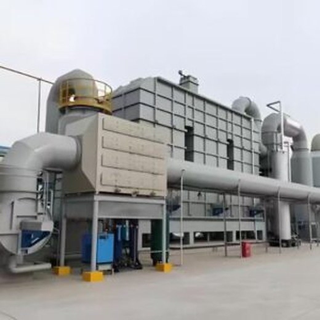
1. Start with the boundary: what changed, and what must be returned to service?
Before a technician closes a door, name the physical boundary. It may include the filter housing, access panels, filter frames, upstream and downstream duct flanges, drains, pressure taps, fan isolation points, bypass dampers, and any temporary covers or tools used during the job.
This boundary prevents an easy mistake: checking only the new element while overlooking the interfaces disturbed to reach it. Compare the as-left arrangement with an approved work pack or a current drawing where available. If no drawing exists, create a simple marked-up record and have the responsible plant team confirm it.
Questions worth resolving before a restart include:
- Is the installed element the intended type, orientation, quantity, and sealing configuration for this location?
- Are frames, clips, rails, doors, and latches fully engaged without forcing a gasket out of position?
- Were pressure taps, drain points, sample ports, temporary blanks, and insulation sections restored?
- Does the job touch only a prefilter, or does it also affect the inlet plenum, fan, bypass, or capture duct balance?
2. Separate visible completion from integrity evidence
Visible completion is necessary, but it is not integrity verification. A clean work area, removed tools, and a signed maintenance ticket prove that a task was closed out; they do not necessarily show that air will follow the intended path when the fan starts.
Build the release record in three layers.
| Evidence layer | What the team checks | Why it matters |
|---|---|---|
| Mechanical condition | Element seating, gaskets, door compression, fasteners, blanking plates, drains, access covers | Establishes that the physical flow path is assembled as intended |
| Instrument readiness | Differential-pressure connections, local indication, alarms or interlocks affected by the work, available trend point | Reduces the risk of interpreting a disconnected or misleading signal as a process problem |
| Controlled operating response | Fan start, staged exhaust admission, unusual noise/vibration, pressure trend, capture behavior, targeted walk-down | Shows how the restored boundary behaves under the site’s approved operating sequence |
Photographs can be helpful, but take them as evidence of a specific condition—not as a substitute for inspection. A clear image of a closed access door is more valuable when it is linked to the housing ID, work order, person checking it, and the time it was observed.
3. Inspect the filter housing and every disturbed interface
The highest-value inspection is often slow and direct. Use the site’s isolation and access rules, then examine the points where air could bypass the element or enter unintentionally. Look for trapped gasket material, uneven frame engagement, damaged seating faces, missing clips, bowed doors, loose bolts, open ports, and displaced internal parts. Do not introduce smoke, powders, or other test media unless the plant’s approved method permits it and the potential downstream impact has been assessed.
Pay particular attention to access doors. A door can look closed while one latch has not reached the required compression. Similarly, a filter may be present but seated on a deformed rail. Record defects as defects; do not turn an uncertain visual observation into a pass because a production restart is waiting.
A practical as-left checklist
- Correct filter reference and quantity checked against the approved work package.
- Flow orientation, if applicable, confirmed from the product marking or drawing.
- Frame-to-gasket and gasket-to-housing contact visually checked around the accessible perimeter.
- All service doors, pressure ports, drains, and inspection covers returned to their intended position.
- Temporary materials, tools, protective sheets, and scaffold restrictions cleared under the site process.
- Any observed corrosion, deformation, condensation, or residue noted for engineering review rather than hidden in a generic “complete” note.
4. Treat differential pressure as context, not a single-pass verdict
Differential pressure is useful only when its measurement points, operating condition, and interpretation are understood. A low value can reflect an open bypass, wrong tap connection, low airflow, a leaking door, or a clean and correctly installed filter. A higher value can reflect increased airflow, a different element, wet contamination, a restriction elsewhere, or an actual loading condition.
For a restart release, record the instrument condition and compare like with like: same airflow state where possible, same fan arrangement, same measurement points, and a known timestamp. If the system does not have a reliable trend, note that limitation and avoid creating a false baseline from one local gauge glance.
Useful record fields include:
| Record item | Capture before or during controlled restart |
|---|---|
| Work boundary | Housing / duct section, work order, filter location, relevant drawings or tags |
| Instrument context | Gauge or transmitter identity, connected taps, reading units, observation time, known limitations |
| Operating state | Fan status, production source status, dampers or bypass condition where allowed to record |
| Observations | Door condition, abnormal sound, vibration, visible air movement, odor report, condensate or residue |
| Decision | Released, released with monitoring, or held for corrective work; responsible role and escalation route |
5. Use a controlled restart sequence rather than a full-load leap
The approved site startup procedure always takes priority. Within that procedure, a staged sequence makes abnormal behavior easier to identify: restore the treatment system and the relevant fan state, confirm required safeguards, introduce exhaust in the permitted steps, then observe the affected boundary before normal production demand obscures the signal.
This is not a request to bypass interlocks or to change safety logic. It is a reminder that a filter change may have altered a part of the exhaust path. If unexpected pressure movement, noise, vibration, door movement, loss of capture, or an alarm occurs, stop at the site-defined hold point and escalate. A clean release record includes held conditions as well as successful checks.
6. Connect the release decision to downstream protection
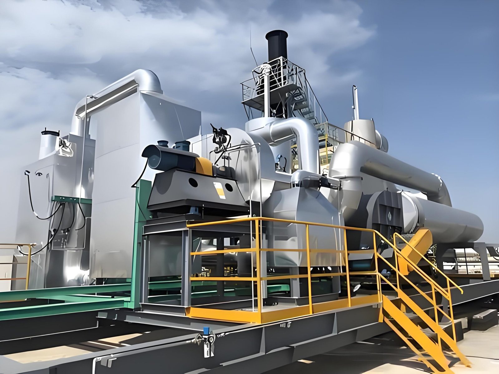
A filter’s job is part of a chain. Depending on the exhaust stream, poor integrity can allow dust, fibrous material, droplets, or other carryover toward fans, ductwork, heat-recovery components, a zeolite concentrator, catalyst, ceramic media, or monitoring points. The likely consequence depends on the actual process chemistry and system configuration; it should not be guessed from a generic RTO diagram.
That is why the release owner should receive both the maintenance result and the operations context. If the stream has changed, if a new coating or solvent is involved, or if condensate and mist are present, review whether the original filter selection and inspection plan still fit the duty. A filter element change cannot correct an upstream contamination problem by itself.
7. Decide what to trend after release
The first stable operating period deserves a defined watch list. Keep it modest and relevant: pressure behavior, fan load or speed if available, capture complaints, door condition on follow-up walk-down, visible residue at accessible points, and any unusual alarm or maintenance callout. Tie the watch period to the actual risk and site procedure rather than copying an arbitrary number of hours.
For a broader stable-operation data structure, see RTO Post-Restart Baseline Data. For the ownership side of the work package, see RTO Filter Change-Out Responsibility. If system resistance changes are a concern, review RTO Pressure Drop and Fan Sizing with the project’s actual airflow data.
FAQ
Is a new filter automatically proof that the system is ready?
No. The element is one part of the boundary. Correct seating, housing closure, restored ports and drains, instrument context, and a controlled operating check still need to be considered under the plant’s approved procedure.
Can one differential-pressure reading confirm that there is no leakage?
No. Differential pressure must be interpreted with airflow, tap connection, bypass position, and measurement condition. It can support a decision, but it is not a universal standalone leak test.
Who should make the restart-release decision?
The responsible role should be defined in the plant’s maintenance and operating procedure. Maintenance, operations, EHS, and engineering may each provide part of the evidence; this article does not assign a universal legal or organizational responsibility.
What if the exhaust stream changed while the filter was being replaced?
Hold the assumption that the old arrangement is still suitable. Review the changed stream with the responsible engineering and safety team before normal operation, especially where dust, mist, condensables, or new process materials are involved.
Request a technical review
SERNO can help structure the equipment-side questions for an RTO, Rotor RTO, RCO, or catalytic-oxidation project. Send the exhaust source description, airflow range, contaminants, current pretreatment arrangement, relevant photos or drawings, and the operating condition that concerns you. We will use that information to discuss a suitable technical scope; any final design and release requirements must be confirmed for the actual site.