
Author: serno_admin

  • Rotor RTO Cold-Condensation Risk: Set a Dew-Point Control Boundary Before Startup

    Rotor RTO Cold-Condensation Risk: Set a Dew-Point Control Boundary Before Startup

    Rotor RTO Cold-Condensation Risk: Set a Dew-Point Control Boundary Before Startup

    A Rotor RTO can be exposed to moisture long before anyone sees liquid at the rotor inlet. A cold duct, a stopped fan, humid make-up air, a wash cycle or a low-temperature section can move the gas temperature below its dew point. The result may be condensation in a low point, wet filter media, re-entrainment, adsorbent performance drift or an unplanned restriction. A temperature number on one instrument is not proof that the complete path is dry enough.

    This guide helps plant teams and buyers define a practical condensation-control boundary before approving a Rotor RTO design, retrofit or restart. It explains what to map, what to measure, what to ask suppliers to document and which release gates should precede process-gas admission. It does not prescribe a universal dew-point margin or guarantee rotor life. The OEM, responsible engineer and site procedures control final limits and actions.

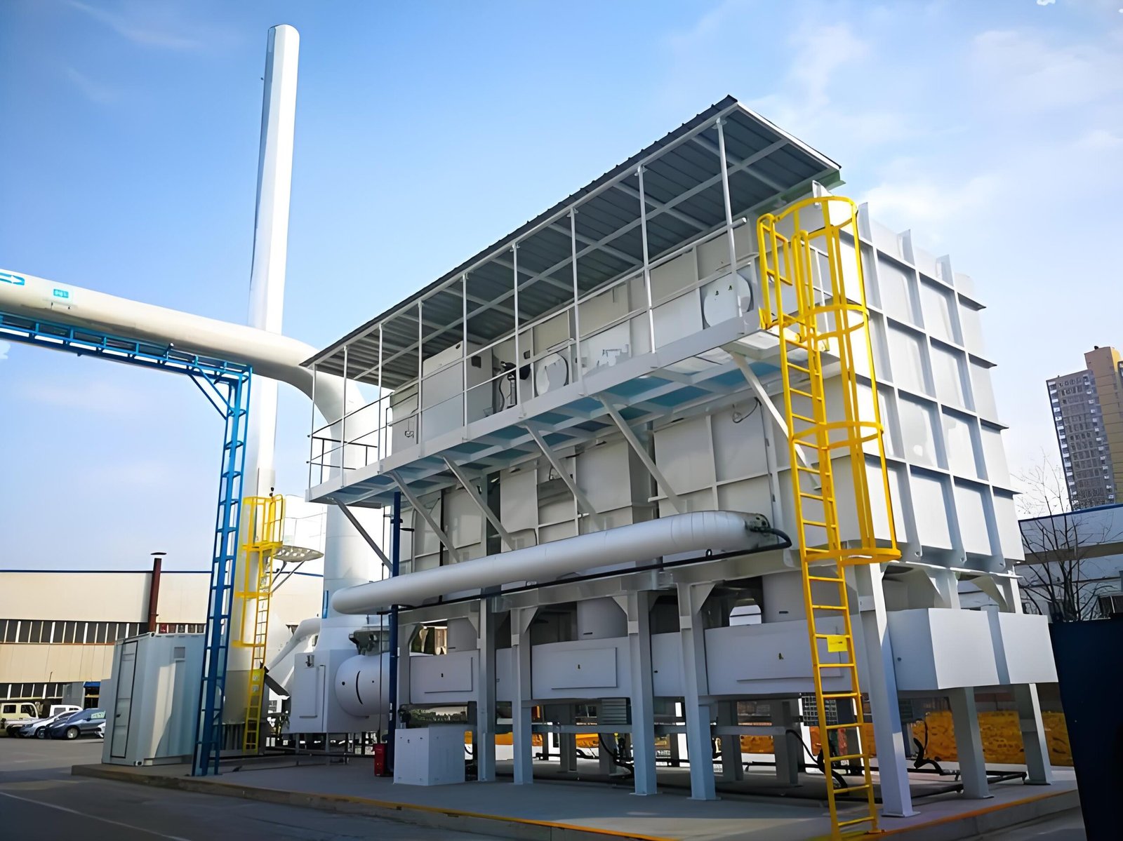
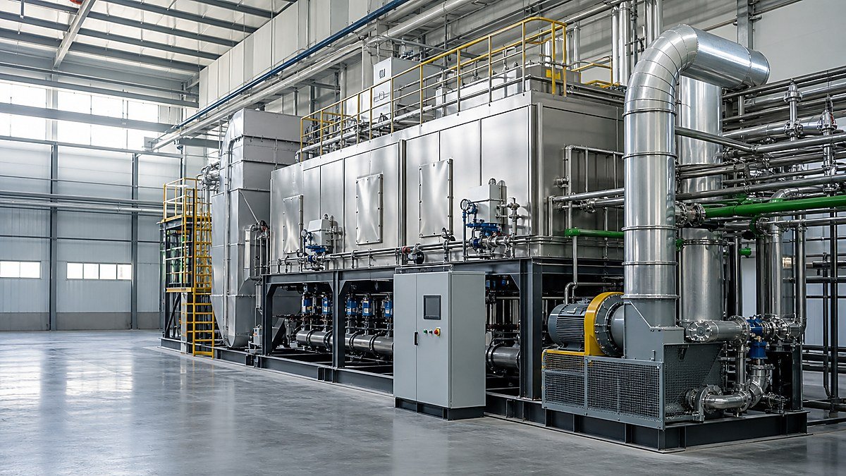
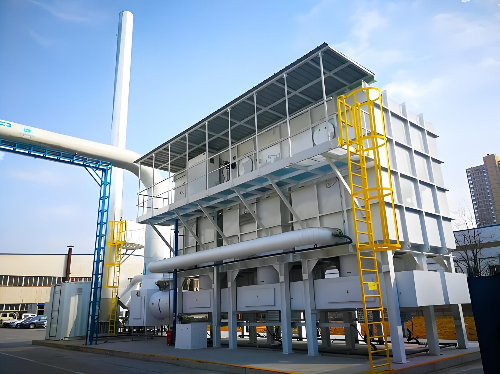
    Industrial RTO equipment and ductwork used to discuss Rotor RTO cold-condensation control

    1. Map where the gas can cross its dew point

    Begin with a source-to-rotor temperature and moisture map. Include permanent headers, temporary branches, cleaning exhaust, fresh-air inlets, outdoor duct runs and any section that can be isolated while another remains cold. Mark insulation, heat tracing, expansion joints, drains, access doors, filters, dampers and instruments on the same drawing.

    For every segment, record the operating case rather than one nominal value:

    • normal production, batch change and seasonal low-load operation;
    • startup after an overnight or planned outage;
    • shutdown, fan trip, damper isolation and restart;
    • water-based cleaning, solvent purge or a wet maintenance task;
    • humid ambient air entering through a bypass or open access point.

    The design question is not simply “What is the inlet temperature?” It is “Which segment can become colder than the gas dew point, and how would collected liquid travel from there to the rotor?”

    2. Separate humidity, condensable VOC and liquid carryover

    Water condensation is only one moisture mechanism. A process stream can also contain condensable VOC, oil aerosol or a cleaning chemical that changes the effective risk. Ask the process owner to identify material families, concentration changes and credible upset cases. The answer should distinguish vapor, aerosol and liquid, because each follows a different control path.

    Risk formWhere it may appearEvidence to requestControl owner
    Humid airOutdoor intake, wash or purge stepTemperature/RH or dew-point record by operating caseProcess and controls team
    Condensable vaporCooled duct, fan inlet, low pointTemperature profile and condensate observation methodMechanical/process engineering
    Liquid carryoverMist eliminator, drain or failed separatorDrain path, inspection record and re-entrainment reviewPretreatment owner
    Wet filter mediaCold filter housing or idle sectionHousing temperature, DP trend and change-out inspectionMaintenance team

    Do not convert an unknown solvent or VOC mixture into a made-up water dew point. Ask the responsible process and equipment specialists to define the appropriate property data and safety controls.

    3. Define the cold-start release gate

    A burner light-off or fan start does not automatically make the rotor path ready. Define a release sequence that proves the relevant duct, filter, drain and rotor-inlet sections have reached their approved condition. The release gate should identify the instrument tag, the reading, the hold time if required by the OEM, and the person who can authorize process-gas admission.

    At minimum, the checklist should cover:

    1. fan and damper status, including any bypass or recirculation path;
    2. temperature and humidity/dew-point readings at the coldest credible section;
    3. filter and mist-control differential pressure compared with its clean baseline;
    4. drain pots, traps and low points checked for blockage or accumulated liquid;
    5. rotor-inlet access or inspection evidence where the design permits it;
    6. alarms, interlocks and historian trends available for the first production case.

    If the design cannot measure the coldest section directly, document the engineering basis for the proxy measurement. A single warm reading near the oxidizer does not clear a cold outdoor duct upstream.

    4. Instrument the boundary, not just the machine

    Instrumentation should answer the failure question. A sensor located after a heated section may show an acceptable temperature while a low point upstream is condensing. Place or specify measurements around the likely transition points: outdoor runs, fan suction, filters, mist eliminators, drains and the rotor inlet.

    Use a traceable log that includes:

    • instrument tag, location and calibration or verification status;
    • gas temperature, ambient temperature and humidity/dew point where applicable;
    • airflow or fan speed at the time of each reading;
    • startup elapsed time and whether process gas was admitted;
    • drain, filter and inspection observations;
    • alarm or action threshold defined by the responsible engineer.

    Trend data is especially important after a fan trip or a long idle period. Record the recovery path, not only the final value. A temperature that eventually recovers may still have allowed liquid to form during the transient.

    5. Control drains and re-entrainment paths

    Condensation control is incomplete if collected liquid cannot leave the system in a controlled way. Review low points, drain legs, traps, collection vessels, heat tracing where applicable and access-panel seals. Confirm that a blocked or full vessel cannot push liquid back into the gas path when the fan ramps.

    Look for these re-entrainment mechanisms:

    • a drain leg without a suitable seal or collection arrangement;
    • poor slope or a pocket that stays wet after the fan stops;
    • fan transients that disturb settled liquid;
    • a cold flange, gasket or access door that admits humid air;
    • a maintenance panel opened while the downstream section is warm and drawing air.

    Inspection notes should identify location and operating context. Water at a low point does not by itself prove rotor damage, but it is evidence that the path and release logic need review before production resumes.

    6. Review abnormal and seasonal cases

    The dew-point boundary must survive more than the design steady state. Ask what happens when production starts in winter, when ambient humidity rises, when a source is isolated, or when a fan trips and restarts. The supplier and plant team should agree which cases are included in the design basis and which require an operator hold point.

    CaseVerifyRecord before release
    Cold morning startupColdest section warms without crossing the approved marginTime-stamped temperature/RH trend and hold-point sign-off
    Fan tripDrainage, damper position and rotor protection logicAlarm sequence, trip time and restart authorization
    Wet cleaning or purgeIsolation prevents moisture migration to the rotorWork permit, isolation proof and dry-out evidence
    Seasonal high humidityControls remain valid at the site ambient conditionAmbient basis, set points and operator response
    Low-load operationFan and heater control do not create a cold pocketAirflow, heater state and rotor-inlet trend

    Avoid a generic statement such as “the system is protected from condensation.” Request the boundary, the case, the measurement and the release decision.

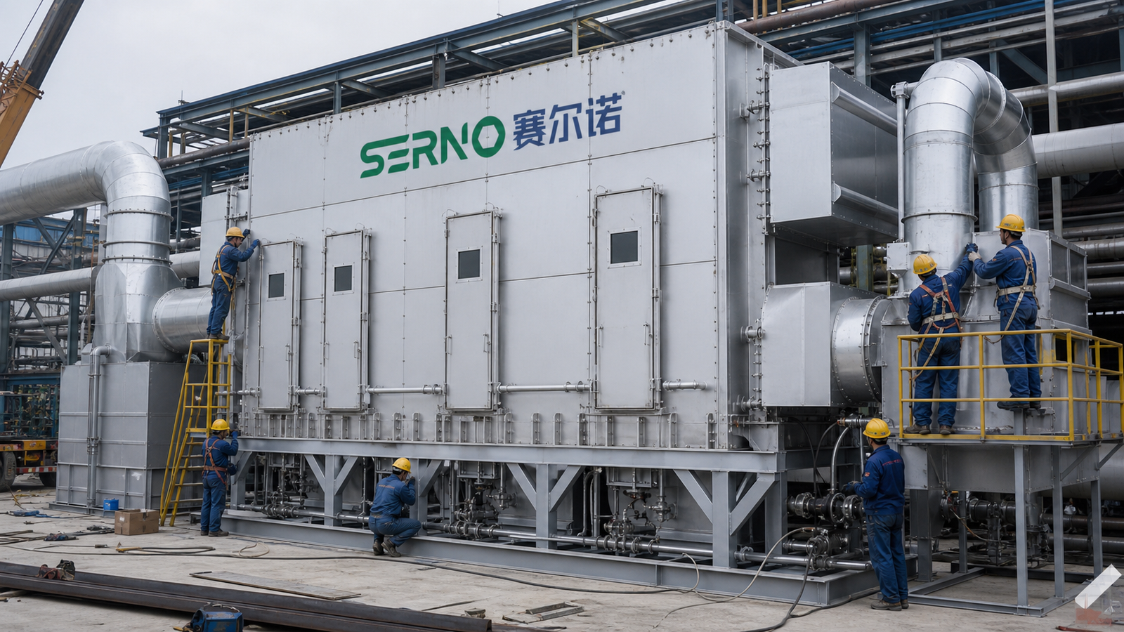
    Industrial duct and burner inspection context for checking Rotor RTO temperature and dew-point evidence

    7. Normalize supplier scope and ownership

    Condensation risk often sits between package boundaries. One supplier may show the rotor and heater, another the fan and duct, while the plant owns drains, insulation, heat tracing and the startup procedure. Put these interfaces into a buyer-controlled matrix before comparing proposals.

    InterfaceClarify in the proposalEvidence at handover
    Duct insulation/heat tracingIncluded length, design basis and control responsibilityAs-built route, test record and control narrative
    Drains and collectionEquipment, seal, freeze/overflow provisionsInspection access and drain test record
    Dew-point measurementTags, locations, ranges and alarm ownershipCalibration/verification record and trend screen
    Startup logicHold points, permissives and bypass behaviorCause-and-effect, procedure and signed trial
    Process change controlWho reviews a new wet or condensable sourceMOC form and updated source map

    The goal is not to force one hardware arrangement. It is to prevent an unowned gap where the rotor is expected to tolerate a condition that no package, instrument or procedure actually controls.

    8. Build a restart evidence pack

    Before calling the system normal, preserve a small evidence pack. Include the approved temperature/dew-point basis, marked-up source map, instrument list, clean DP baseline, drain and low-point inspection notes, startup trend, alarms and any deviation disposition. Link the evidence to the operating case and date.

    When a deviation occurs, record what was observed, what was isolated, what was inspected and who released the next step. Do not infer rotor damage, efficiency loss or remaining service life without an appropriate inspection or test. A disciplined evidence pack lets the OEM and site engineer decide whether the issue is a sensor problem, a drain problem, a cold spot or a broader process change.

    FAQ

    What is a safe universal dew-point margin for a Rotor RTO?

    There is no universal value that can be applied to every rotor, duct, VOC mixture and ambient condition. The selected OEM and responsible engineer should define the design basis, measurement uncertainty, transient case and action threshold.

    Can a warm temperature at the rotor inlet prove there is no condensation upstream?

    No. A downstream warm reading can miss a cold outdoor run, filter housing or low point. The measurement plan should cover the coldest credible sections or document a defensible engineering proxy.

    Should heat tracing always be added?

    Not automatically. Heat tracing, insulation, drainage, airflow control and operating logic are design choices that depend on the route, ambient condition, material properties and site procedures. Ask for the basis and ownership of each measure.

    What should buyers request from an RTO supplier?

    Request a source-to-rotor temperature/moisture boundary, transient cases, instrument locations, drain and insulation scope, startup release gates, alarm ownership and handover evidence. Compare those items before comparing price alone.

    Talk with SERNO

    If you are reviewing a Rotor RTO retrofit, startup sequence or condensation concern, share the source map, airflow cases, ambient range and available temperature/DP trends with SERNO. We can help structure the engineering questions and scope boundaries; final limits, controls and approvals remain with the responsible engineer, OEM and site team.

  • Rotor RTO Pretreatment Evidence: Prove Mist and Dust Control Before the Zeolite Rotor

    Rotor RTO Pretreatment Evidence: Prove Mist and Dust Control Before the Zeolite Rotor

    Rotor RTO Pretreatment Evidence: Prove Mist and Dust Control Before the Zeolite Rotor

    A zeolite rotor concentrator is often discussed as the heart of a Rotor RTO system. In practice, the equipment in front of the rotor determines what reaches its adsorbent surface. Paint mist, oil aerosol, dust, condensable vapor or a process-side change can create fouling, pressure-drop growth, carryover or an unstable operating window. A filter symbol on a P&ID is not proof that the pretreatment boundary is adequate.

    This guide shows plant teams and buyers how to define and evidence the pretreatment boundary before approving a Rotor RTO design, retrofit or corrective scope. It does not prescribe a filter grade or guarantee rotor life. The OEM, responsible engineer and site procedures control final selection, access, sampling and change-out.

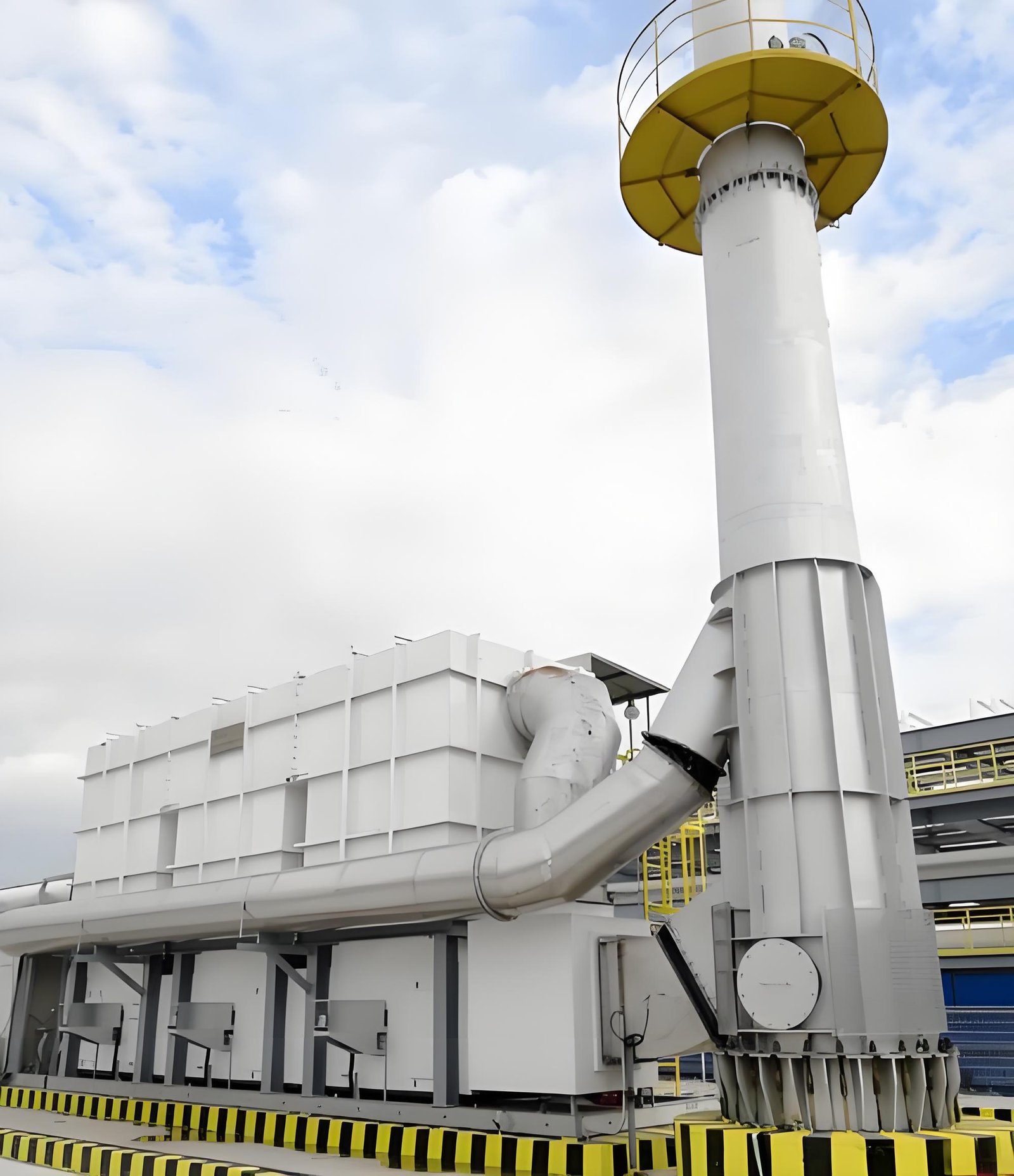
    Industrial oxidizer equipment and connected ductwork used as context for Rotor RTO pretreatment protection

    1. Start with a source-to-rotor contaminant map

    List every source that can connect to the rotor inlet, including temporary headers, cleaning vents, maintenance exhaust and future production branches. For each source, record the process, material family, expected airflow pattern and credible contaminant forms. A source map should distinguish continuous, batch and abnormal releases rather than averaging them into one generic VOC number.

    At minimum, ask:

    • Can the source produce liquid droplets, sticky aerosol, dust, fibers or condensable vapor?
    • What changes when the recipe, supplier, coating, resin or cleaning chemical changes?
    • Can a bypass, drain, low point or failed damper send material around the intended pretreatment?
    • What happens during startup, shutdown, upset or a fan trip?
    • Which streams are allowed to connect, and who authorizes a new connection?

    The map is the design basis for the pretreatment train. Without it, a supplier can size a filter while leaving the contaminant question undefined.

    2. Define the pretreatment train by function

    Describe each stage by the risk it controls, not only by its equipment name. A typical review may include source capture, coarse filtration, fine filtration, mist elimination, cooling or condensation control, drains, access sections and differential-pressure instrumentation. The exact arrangement depends on the exhaust chemistry and the selected rotor.

    FunctionEvidence to requestBuyer question
    Capture and segregationSource list, damper logic, hood or header drawingsCan an abnormal source bypass the protection boundary?
    Dust and particulate controlFilter type, housing details, change-out method, DP rangeWhat indicates loading before carryover occurs?
    Mist and aerosol controlDroplet/aerosol basis, eliminator arrangement, drain pathWhere does liquid go, and how is re-entrainment prevented?
    Condensate managementTemperature profile, low points, drains, heat tracing if applicableCan condensate reach the rotor during cold or transient operation?
    MonitoringDP tags, alarm limits, sampling points, inspection accessWhich reading triggers action and who owns it?

    Functional language exposes missing interfaces more clearly than a list of component names.

    3. Treat differential pressure as a trend, not a single number

    Pressure drop across a filter or mist eliminator is useful only when the measurement boundary is clear. Record the clean baseline, airflow or fan condition, temperature, instrument status and the date of each reading. A high value may indicate loading; a sudden low value can also indicate a damaged element, bypass or a disconnected impulse line.

    Create a simple log with:

    1. Section and instrument tag.
    2. Airflow or fan speed at the time of reading.
    3. Clean/reference condition and current value.
    4. Alarm or action threshold defined by the responsible engineer.
    5. Filter, drain or cleaning action taken.
    6. Rotor-inlet observation and downstream consequence, if any.

    Do not invent a universal replacement threshold. The correct limit depends on the selected hardware, flow range, dust or mist loading and the supplier’s instructions.

    4. Check drains, low points and re-entrainment paths

    Mist control is incomplete if collected liquid has nowhere controlled to go. Inspect low points, drain legs, traps, collection vessels and access doors under an approved procedure. Confirm that drains remain usable during the operating temperature range and that a blocked or full vessel cannot push liquid back into the airflow.

    Review the conditions that can create re-entrainment:

    • excessive face velocity or poor flow distribution;
    • a drain without a suitable seal or collection arrangement;
    • fan transients that disturb settled liquid;
    • cold sections where vapors condense unexpectedly;
    • maintenance panels or gaskets that leak around the intended path.

    Photographs and inspection notes should identify location and operating context. A wet surface alone does not prove rotor damage, but it is a reason to preserve evidence and review the path.

    5. Verify transient and abnormal cases

    The pretreatment boundary must be reviewed during more than the design steady state. Ask what happens when production starts, a batch changes, a fan ramps, a source is isolated, or a process upset sends an unusual concentration or aerosol load toward the header.

    CaseWhat to verifyRecord
    StartupFilter and mist-control readiness before source admissionRelease checklist and DP baseline
    Recipe or material changeNew aerosol, condensable or dust riskChange record and source review
    Fan trip or low flowDrainage, cooling and rotor protection logicAlarm sequence and restart gate
    High-loading eventIsolation or diversion responseTime, source, actions and inspection
    Planned shutdownClean-air purge and exposed-surface conditionOutage work pack and photos

    These cases connect pretreatment design to operations. The Rotor RTO shutdown preparation guide covers the later outage stage; this article focuses on the evidence before contaminants reach the rotor.

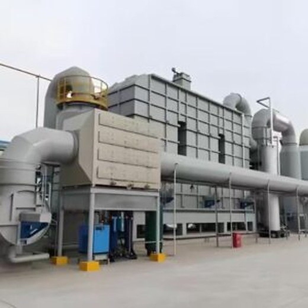
    Industrial maintenance and inspection workspace supporting review of Rotor RTO filters, drains and differential-pressure evidence

    6. Make inspection access part of the scope

    A pretreatment device that cannot be inspected safely will eventually become an assumption. The scope should show access doors, lighting, drain access, lifting or change-out clearance, sample points and the location of DP instruments. Clarify whether the buyer, OEM or maintenance contractor owns inspection and consumables.

    During a permitted inspection, separate observations from conclusions. Record filter condition, deposits, liquid evidence, gasket condition, drain status and instrument health. Link each observation to a source, date and operating case. Do not open hazardous equipment or remove elements outside the approved isolation and permit process.

    The complete RTO system-scope guide is useful when checking that access, controls, drains and interfaces have not disappeared between the process design and the quotation.

    7. Questions to ask before approving a pretreatment scope

    • Which contaminant forms and source changes are included in the design basis?
    • Which stages protect against dust, mist, condensables and accidental liquid carryover?
    • What are the clean/reference DP values, alarm logic and inspection response?
    • How are drains sealed, monitored and protected from re-entrainment?
    • What happens during startup, fan trips, batch transitions and abnormal loading?
    • Which consumables, access platforms, lifting aids and spare elements are included?
    • What evidence will be recorded before the rotor is released for production gas?
    • Which assumptions require a process sample, pilot test or OEM confirmation?

    A low equipment price can conceal missing access, drains, instruments or change-out responsibility. Normalize the scope before comparing bids.

    FAQ

    Why does pretreatment matter for a zeolite rotor?

    Pretreatment controls material that could foul, wet, obstruct or otherwise stress the rotor. The specific risk depends on the process and rotor design; the source map and operating evidence should define it.

    Is a rising filter pressure drop always bad?

    Not automatically. A trend can indicate loading, but instrument faults, airflow changes, damaged elements or bypass conditions can produce misleading readings. Compare like-for-like conditions and follow the supplier’s limits.

    Can a mist eliminator replace a dust filter?

    They address different risks. A mist device is not automatically a particulate-control stage, and the correct combination depends on particle and droplet characteristics, flow and the rotor supplier’s design basis.

    What should be documented after a process change?

    Update the source and material map, review aerosol/condensable risks, confirm pretreatment capacity and controls, and record the approved release evidence before reconnecting the source.

    Should buyers specify only a filter efficiency percentage?

    No. A useful scope also defines contaminant form, airflow range, housing/access, DP monitoring, drains, change-out responsibility and transient cases. A percentage without the test basis can be misleading.

    A practical next step for plant teams

    Before requesting a Rotor RTO pretreatment quotation, assemble a source-and-material map, recent DP and drain records, transient operating cases, photographs from approved inspections and the list of planned process changes. SERNO can review that boundary with a buyer and identify which assumptions need supplier confirmation. OEM instructions, site permits and the responsible engineer remain controlling.

  • RCO Catalyst Poisoning Diagnosis: Separate Catalyst Deactivation from an Upstream Process Change

    RCO Catalyst Poisoning Diagnosis: Separate Catalyst Deactivation from an Upstream Process Change

    RCO Catalyst Poisoning Diagnosis: Separate Catalyst Deactivation from an Upstream Process Change

    An unexpected outlet VOC trend, higher support-fuel demand, or a narrower stable operating window can lead a plant team to one fast conclusion: the RCO catalyst is spent. That conclusion may be correct, but it is not yet a diagnosis. A regenerative catalytic oxidizer is a system of exhaust collection, pretreatment, valves or dampers, heat-recovery media, burner controls, measurement points, and catalyst. A process change upstream can resemble catalyst deactivation; a catalyst problem can also be made worse by a contaminant path that remains unaddressed.

    This guide gives plant teams and industrial buyers an evidence sequence for investigating possible RCO catalyst poisoning or deactivation. It is not an instruction to remove catalyst, alter temperatures, or bypass safety controls. Those actions require the equipment supplier’s instructions, plant permit system, and responsible engineer. The goal is to separate observations from assumptions before a service or replacement scope is defined.

    Regenerative catalytic oxidizer equipment and connected ductwork at an industrial VOC treatment installation

    1. Confirm the symptom and its measurement boundary

    Begin with the exact observation. “Poor performance” is too broad to compare over time. State whether the issue is an outlet VOC reading, a compliance-monitor alarm, fuel use, bed-temperature behavior, pressure drop, odor complaint, startup instability, or an operating limit imposed by the controls.

    For each observation, identify the measurement boundary:

    • the instrument tag, sample point, sample conditioning path, calibration status, and time window;
    • production rate, exhaust flow, VOC family, and any connected exhaust sources at the same time;
    • RCO inlet/outlet temperatures, chamber or bed temperature where available, pressure drop, fan load, and valve/damper feedback;
    • support-fuel command and actual fuel-flow record, if the site records it;
    • active alarms, interlocks, manual overrides, bypass positions, and maintenance work.

    A single high reading is a trigger for review, not proof of catalyst poisoning. Compare a stable, like-for-like operating case before and after the concern. If the sample system is not trusted, document that limitation first; a laboratory-quality interpretation cannot repair a poor sampling boundary.

    2. Do not assume every RCO change is a catalyst problem

    Catalyst activity can decline through fouling, masking, chemical poisoning, thermal exposure, mechanical damage, or normal aging. However, several non-catalyst conditions can produce similar symptoms. The investigation should test the system boundary before it focuses only on the catalyst bed.

    Observed changeOther plausible causes to testEvidence that narrows the question
    Outlet VOC trend risesSample-system issue, valve leakage, bypass, changed inlet load, inadequate temperatureCalibrations, valve feedback, inlet/outlet paired samples, stable-case trend
    Support-fuel demand risesLower VOC heat value, excess airflow, heat loss, changed operating modeProduction recipe, airflow, temperatures, insulation/duct walkdown
    Pressure drop increasesFilters, media fouling, duct restriction, condensateDifferential-pressure trend, filter record, inspection and drain status
    Stable window narrowsControl tuning, sensor drift, fan change, process variabilityAlarm history, controller mode, drive speed, source-by-source load record
    Temperature profile shiftsThermocouple fault, heat-recovery issue, airflow distribution, catalyst conditionIndependent temperature check, valve sequence, flow balance evidence

    The RTO Outlet VOC Spikes guide is useful as a general fault-isolation discipline: make one controlled comparison at a time rather than changing fuel, airflow, dampers, and process loading together.

    3. Build a before-and-after operating case

    Choose one recent period that plant teams regard as stable and one period containing the concern. Avoid comparing different products, shifts, source combinations, weather conditions, or startup phases without labeling the difference. The data pack does not need to be perfect; it must make its gaps visible.

    Minimum comparison fields

    1. Date, shift, production recipe or coating/solvent family, and connected exhaust sources.
    2. Exhaust flow indication, fan speed/load, and pressure drop across the relevant system sections.
    3. Inlet and outlet VOC method and time basis, including calibration or laboratory reference where available.
    4. Key temperatures, support-fuel command/flow if recorded, and the control mode.
    5. Valve/damper feedback, bypass status, alarm history, and manual interventions.
    6. Pretreatment status: filters, demisters, condensers, scrubbers, drains, and any recent change-out.

    The practical question is not “is every value normal?” It is “what changed when the symptom appeared, and how certain are we?” A batch process with a new solvent blend may need a source-by-source review; a continuous process may show the change more clearly through trends.

    4. Review contaminant pathways before discussing replacement

    Catalysts can be affected by materials that reach the catalyst surface or the wider flow path. The relevant contaminants are site-specific. Depending on the catalyst formulation and process, an engineering review may consider particulate, sticky aerosol, oil mist, condensable vapors, silicon-containing materials, sulfur- or phosphorus-containing compounds, halogenated species, metals, and corrosive compounds. Listing a compound family does not prove it is present or that it is the cause.

    Map the path from each production source to the RCO. Include common headers, temporary connections, maintenance vents, process changes, and any upstream equipment that may be bypassed or operating differently. Then review the evidence:

    • safety data sheets and current material inventory, including additives and cleaning agents;
    • process-change records, supplier changes, new recipes, and abnormal events;
    • pretreatment differential pressure, drain/cleaning records, and visible carryover evidence;
    • duct low points, mist collection, and any points where condensate can re-entrain;
    • maintenance observations from inlet ductwork, filters, and accessible surfaces.

    Do not request a catalyst sample simply because the word “poisoning” has been used. A sampling plan must define safety, representativeness, chain of custody, test question, and what decision the result will support. Coordinate it with the catalyst and RCO supplier.

    Industrial maintenance and inspection workspace supporting evidence review for a VOC treatment system

    5. Inspect safely and keep the evidence attributable

    If an approved outage or inspection window exists, the work pack should distinguish visual observations from conclusions. Record locations, lighting, orientation, date, and observer. A photograph of discoloration may indicate that further review is needed; it does not identify a chemical or a loss of activity by itself.

    Suggested evidence categories are:

    • inlet duct, drains, filters, mist eliminators, and accessible heat-recovery surfaces;
    • catalyst module or bed location only when access is authorized and equipment is safe;
    • gasket, seal, valve, and bypass condition where a flow shortcut could matter;
    • instrument condition and sample-system maintenance;
    • any residue, corrosion, dust, or liquid evidence, linked to the process period and source map.

    Preserve the baseline too. An RCO proposal or service report should be able to show what was observed, which evidence was measured, and which items remain assumptions. This protects both the buyer and the engineering team from replacing a catalyst while leaving the upstream cause in place.

    6. Decide the next test before changing the operating point

    Avoid broad, simultaneous adjustments. Increasing temperature, changing airflow, cleaning filters, and changing a solvent recipe at once may obscure the root cause and can create a safety or permit concern. Instead, choose a controlled, approved next step that answers one question.

    Diagnostic questionExample controlled next stepDecision use
    Is the outlet measurement credible?Verify the analyzer/sample path against the approved reference methodConfirms whether the symptom needs further process investigation
    Did inlet loading change?Compare paired stable-case data and material/source recordsSeparates a feed change from apparent conversion loss
    Is there a bypass or sequencing issue?Review command and field feedback under approved conditionsIdentifies a flow path that could avoid the intended treatment route
    Is pretreatment protecting the oxidizer?Inspect approved accessible points and compare DP/drain recordsDetermines whether an upstream carryover risk needs correction
    Is catalyst evaluation justified?Agree an OEM-supported inspection or test planDefines whether specialist assessment is appropriate

    The point is not to force a diagnosis remotely. It is to produce an evidence package that supports a safe engineering decision. The RTO Performance Verification guide provides a compatible way to frame operating cases, instruments, deviations, and release criteria.

    7. Questions buyers should ask before approving a catalyst scope

    When evaluating an RCO catalyst inspection, service, or replacement proposal, request the basis of the recommendation. A useful scope makes the unknowns explicit.

    • Which observed symptom is being addressed, and what evidence ties it to catalyst condition?
    • Which non-catalyst causes were checked, excluded, or left unverified?
    • What inlet composition, contaminant assumptions, flow range, temperature range, and pretreatment condition form the design basis?
    • What inspection, sampling, laboratory, or performance-verification method is proposed, and who owns safety and chain of custody?
    • Does the scope include upstream corrective actions, filter/mist-control work, cleaning, sealing, or valve verification where evidence indicates a need?
    • What will be recorded during recommissioning, and what conditions trigger escalation rather than acceptance?
    • Which manufacturer instructions, site procedures, and permits control catalyst handling and restart?

    A quote that only states a catalyst volume or a guaranteed outcome without a process basis leaves material risk with the buyer. Conversely, a thorough diagnostic pack should not be used to promise a result before process data, equipment condition, and the final scope have been verified.

    FAQ

    What is catalyst poisoning in an RCO?

    In general terms, it describes a loss or reduction of useful catalyst activity caused by exposure to compounds that interfere with the catalyst surface or chemistry. The actual mechanism, severity, reversibility, and remedy depend on the catalyst formulation, exposure history, operating conditions, and evidence from the specific system.

    Can higher fuel use prove that the catalyst is deactivated?

    No. Higher fuel use can also follow lower VOC heat value, higher airflow, heat loss, different operating mode, poor measurement, or controls issues. Compare stable operating cases and verify the measurement boundary before assigning the cause.

    Should a plant raise temperature to compensate for suspected catalyst loss?

    Only under the approved operating envelope and with the equipment supplier and responsible engineer. An unreviewed temperature change can affect safety, equipment, permits, emissions, and the evidence needed for diagnosis.

    What process information is most useful to an RCO supplier?

    Provide source list, flow range, current material and solvent information, safety data sheets, inlet/outlet measurement method, trend data, temperatures, pressure drop, pretreatment condition, alarms, process changes, and photographs from approved inspections. State what is unknown instead of filling gaps with assumptions.

    Is catalyst replacement always the first remedy?

    No. The correct next step may be a measurement check, source-change review, valve or bypass correction, pretreatment improvement, approved cleaning, specialist catalyst evaluation, or replacement. The evidence and OEM guidance should determine the sequence.

    A practical next step for plant teams

    Before requesting an RCO catalyst scope, assemble a short evidence pack: two comparable operating periods, the source and material map, pretreatment history, instrument and alarm records, pressure-drop and temperature trends, and approved inspection observations. SERNO can review this process boundary with a buyer to identify what operating information is still needed for a technically grounded RCO discussion. Site procedures, OEM instructions, and the responsible engineer remain controlling.

  • Rotor RTO Shutdown Preparation: Protect the Zeolite Concentrator Before a Planned Outage

    Rotor RTO Shutdown Preparation: Protect the Zeolite Concentrator Before a Planned Outage

    Rotor RTO Shutdown Preparation: Protect the Zeolite Concentrator Before a Planned Outage

    A zeolite rotor concentrator changes the shutdown question. A conventional oxidizer can be taken offline after its approved purge and cooldown sequence, but the rotor section also contains adsorbent media, seals, bearings, purge air paths and a housing where dust or condensate can accumulate. If the process exhaust is isolated too early, humid air or residual solvent can remain where the next startup depends on stable adsorption and desorption.

    This guide is for a planned production outage—not an emergency trip. The exact sequence must follow the equipment supplier’s instructions, the plant permit-to-work system and the site’s lockout/tagout (LOTO) procedure. The objective is simple: leave the rotor dry enough, clean enough, mechanically supported and fully documented for a controlled restart.

    Industrial zeolite rotor concentrator and RTO installation prepared for a planned shutdown inspection

    1. Define the outage case before touching a valve

    “Shutdown” can mean a lunch break, a weekend, a multi-week maintenance outage or a process change while the VOC system remains electrically live. Those cases do not have the same risk. Write the intended state in a one-page outage sheet and have operations, maintenance, EHS and the system owner sign it.

    Record the boundary conditions

    Capture the last stable operating case and the planned isolation points:

    • production lines connected to the rotor and which ones will remain active;
    • expected duration and ambient temperature/humidity range;
    • VOC family, dust/mist exposure and any upstream wet scrubber or condenser status;
    • rotor inlet/outlet temperature, purge temperature, fan status and differential pressure;
    • alarm, interlock or bypass status at the moment of handover;
    • energy sources to isolate: electrical, thermal, pneumatic, fan inertia and stored pressure.

    Do not infer that a closed process damper is a verified isolation. Identify the damper tag, its fail position, the proof method and the person responsible for checking it. If another exhaust source can backflow through a common header, include that path in the boundary review.

    2. Finish the clean-air and solvent-displacement phase

    Before process gas is removed, the rotor should complete the supplier-approved adsorption/desorption cycle at the specified clean-air flow. The purpose is to displace residual VOC vapour from accessible ductwork and reduce the load held in the rotor and downstream oxidation section. A clean-air purge is not a substitute for LEL controls, gas testing or an approved emergency procedure.

    Use a written hold point rather than a timer alone. Operations should confirm:

    1. process exhaust has stopped or has been diverted to the approved route;
    2. clean-air purge fan and damper feedback agree with the command;
    3. temperature and differential-pressure readings are stable enough to compare with the last normal case;
    4. no high VOC, high temperature, bearing, seal or fan alarm is active;
    5. the permit issuer has accepted the measured atmosphere and isolation plan.

    If the rotor is still receiving a variable solvent load, extending the purge may be safer than beginning mechanical work. Record the actual flow indication and the sample time; “fan on” by itself is not evidence of adequate displacement.

    3. Control moisture, condensation and dust

    Moisture is a shutdown risk because a cool rotor housing can reach dew point while the plant is idle. Water can carry soluble contaminants into the adsorbent, promote corrosion at metal interfaces or freeze in cold climates. Dust and sticky mist can also become harder to remove after a long idle period.

    Make the dew-point decision explicit

    Compare the expected metal temperature with the local dew point during the outage. Where the design permits, keep a dry, filtered air sweep or approved low-flow ventilation until the housing is below the specified safe condition. Where it does not, isolate and seal the housing exactly as the supplier requires. Never improvise a heater or bypass around a safety interlock.

    Check the complete moisture path:

    CheckEvidence to keepWhy it matters
    Upstream drain, demister or scrubberDrain status, inspection note, last clean-outPrevents liquid carryover into the rotor
    Low points in ductworkPhoto or signed walkdownFinds trapped condensate before isolation
    Housing access doors and gasketsDoor/bolt condition and seal observationLimits humid-air ingress
    Instrument-air qualityPressure and dew-point record if availableProtects pneumatic dampers and seals
    Filter and mist-eliminator conditionDifferential pressure and visual checkReduces dust loading during restart

    If a plant has no reliable dew-point measurement, state that limitation in the outage record and use the conservative procedure approved for the equipment. Do not turn an estimate into a guarantee.

    4. Cool down in a way that protects seals and bearings

    Rotor RTO equipment contains hot surfaces and rotating hardware that respond differently to a fast stop and a controlled cooldown. Follow the approved ramp and minimum lubrication/turning requirements. A bearing can be stationary while the housing is still thermally expanding; a seal can appear normal at ambient temperature yet rub when the rotor is restarted.

    Record at least:

    • rotor-drive status, speed or turning-device status;
    • bearing temperature and any vibration indication;
    • rotor housing temperature at the supplier-defined points;
    • purge-air temperature and fan/damper feedback;
    • differential pressure across the rotor and key filters;
    • the time each hold point was reached.

    Do not open inspection doors until the permit confirms the surface temperature and atmosphere are safe. If the drive must rotate intermittently during a long outage, document the interval, lubrication requirement and responsible person instead of leaving it as an informal shift task.

    Industrial maintenance inspection of rotor RTO components before an outage

    5. Isolate energy and prove the mechanical state

    The LOTO plan should match the actual equipment boundary. Typical sources include the rotor motor and heater, process and purge fans, compressed air, pneumatic actuators, hot-gas paths and gravity or stored pressure in ductwork. Each isolation needs a tag, lock owner and proof test.

    After isolation, verify the mechanical state without defeating protection:

    • damper position indication agrees with the field position;
    • fan coast-down is complete and backflow paths are controlled;
    • actuator air is isolated and residual pressure relieved;
    • rotor drive cannot start from a remote or automatic command;
    • access doors, drains and inspection ports are secured for the outage condition.

    The existing RTO Shutdown and Restart Checklist gives a broader oxidizer sequence. Use this rotor-specific guide as an addendum, not as permission to replace the site’s approved LOTO or emergency instructions.

    6. Create an inspection baseline before the outage grows

    The best outage record is a comparison set. Photograph the rotor housing, access seals, drain points, filter faces, fan inlet and visible ductwork under the same lighting and angle used for previous inspections. Save instrument trends—not only a screenshot of the final value.

    Flag deviations that need an owner and a decision date:

    • rising rotor differential pressure;
    • visible dust, oil mist or liquid staining;
    • seal rub marks, unusual noise or drive vibration;
    • unexplained temperature imbalance between rotor sectors;
    • damaged insulation, loose lagging or corroded fasteners;
    • a damper that reaches command but lacks position proof.

    If cleaning or media work is proposed, define the acceptance evidence before work starts: photos, measured pressure drop, seal clearance check, bearing condition, filter replacement record and a signed restart release. This prevents a “looks clean” handover from becoming an untraceable change.

    7. Plan the restart gate while the plant is still online

    Restart readiness should be a gate with named sign-offs. Before process gas is re-admitted, confirm the rotor is reassembled, drains are closed or routed, filters are installed, instruments are calibrated or clearly tagged for verification, and all temporary blinds or covers are controlled. Restore utilities in the approved order and prove the automatic sequence in clean air first where required.

    The first process run should use a defined operating case. Record flow, temperature, rotor speed, purge ratio or flow indication, differential pressure, fan load and outlet-monitor status. Compare the result with the pre-outage baseline; a new normal should not be declared until deviations are explained. The RTO Post-Restart Baseline Data article provides a compatible recording framework.

    Suggested release matrix

    GateMinimum evidenceOwner
    Mechanical completeWork pack closed, doors/gaskets checked, guards fittedMaintenance
    Dry and cleanDrain status, filter record, moisture decision documentedOperations / EHS
    Controls readyInterlocks tested, damper feedback proven, alarms acknowledgedControls
    Utilities stablePower, instrument air and fans available at approved conditionOperations
    Clean-air run acceptedSequence completes without abnormal temperature, DP or vibrationSystem owner
    Process gas releaseDefined case, trend capture and escalation contacts readyOperations / EHS

    FAQ

    Can a rotor RTO be left full of ambient air during a long outage?

    Only if that state is explicitly allowed by the equipment supplier and the site’s moisture-control assessment. Ambient air may be acceptable in one climate and risky in another. Use dew point, housing temperature, contamination risk and the approved sealing or dry-air procedure to make the decision.

    Should the rotor keep turning after process exhaust is isolated?

    That depends on the drive, bearing and preservation design. Some systems require controlled turning or a turning gear; others require a defined stationary condition. Follow the supplier’s interval and lubrication instructions and record who owns the task.

    Is a clean-air purge enough to declare the system gas-free?

    No. Purge completion is one operating hold point. Gas testing, LEL controls, permit authorization and LOTO proof remain mandatory according to the site procedure.

    What if differential pressure is higher after restart?

    Stop and compare the trend with the pre-outage baseline. Check filter installation, damper position, condensate, dust carryover and seal condition before changing fan settings. A higher reading is a symptom to investigate, not a reason to claim a new design value.

    What information should a buyer request from an integrator?

    Request the rotor-specific shutdown and preservation sequence, boundary and isolation drawing, moisture/dew-point assumptions, turning-gear or lubrication requirements, inspection points, restart release matrix and the data fields to be trended. These documents show whether the proposed system can be operated and maintained, not only purchased.

    A practical next step for plant teams

    Before the next planned outage, assemble one evidence pack: last stable trends, the rotor and duct isolation drawing, dew-point or humidity information, filter and drain condition, LOTO boundary, inspection photographs and the restart release matrix. SERNO can review that pack with the exhaust-source list and help identify which rotor RTO operating cases need confirmation before a proposal or outage plan is finalized. Equipment selection and any site-specific sequence should remain subject to verified process data and the responsible engineer’s approval.

  • How to Compare RTO Proposals: A Scope-Normalization Matrix for Industrial Buyers

    How to Compare RTO Proposals: A Scope-Normalization Matrix for Industrial Buyers

    How to Compare RTO Proposals: A Scope-Normalization Matrix for Industrial Buyers

    Two RTO proposals can describe similar treatment capacity yet include very different assumptions, interfaces, controls, field work, and evidence. If those differences stay hidden inside supplier notes, the lowest line-item price may be attached to a narrower scope or a different operating case. The practical first step is not to rank suppliers; it is to make the proposals comparable.

    This guide gives industrial buyers and project teams a disciplined way to normalize RTO proposals before a technical-commercial decision. It is an evaluation framework, not a substitute for the plant’s design basis, hazardous-area assessment, permit obligations, contract review, or qualified engineering judgment. Record what each proposal actually states, what it assumes, and what still needs confirmation.

    Industrial RTO equipment used as a visual context for an RTO proposal scope review

    1. Start with one buyer-controlled design basis

    Do not allow each bidder to define the duty independently. Issue a common data sheet or clarification register that identifies the source streams, expected operating cases, available measurements, and project constraints. When a value is estimated, label it as estimated rather than presenting it as a guaranteed fact.

    At minimum, align the comparison around:

    • exhaust flow range and the basis of that flow measurement;
    • VOC species information, concentration range, and expected loading cases;
    • temperature, moisture, particulates, mists, acid gases, or other contaminants that affect pretreatment and materials;
    • source simultaneity, batch events, startups, shutdowns, and future operating changes;
    • site utilities, footprint, elevation, access, civil constraints, and tie-in windows; and
    • the buyer’s requested evidence, operating philosophy, and handover documents.

    A proposal based on an incomplete data set can still be useful for budgeting. It should simply be compared as a conditional concept, with its missing inputs and design assumptions visible.

    2. Build a scope-normalization matrix before discussing price

    Create one row per decision point. Give every bidder the same columns: included, excluded, assumed, supplied by buyer, and clarification needed. Avoid scoring a blank cell as an inclusion.

    Comparison rowWhat to normalizeEvidence to request
    Design caseFlow, loading, temperature, contaminants, operating hours, simultaneous sourcesDesign-basis sheet and assumptions list
    Treatment trainRTO configuration, pretreatment, dilution, heat recovery, stack pathProcess description and equipment list
    Fan and duct interfacesFan duty, pressure basis, duct extent, supports, dampers, insulationInterface sketch and pressure-drop breakdown
    Controls and safetyPLC/HMI scope, instruments, alarms, permissives, cause-and-effect boundariesControls narrative and I/O or responsibility list
    Site executionCivil works, lifting, installation, commissioning attendance, trainingBattery-limit drawing and field-services list
    Verification and recordsStartup records, test support, manuals, drawings, spare-parts listDeliverables schedule and acceptance wording

    The purpose is not to force identical equipment. It is to expose where different technical solutions rely on different inputs, boundaries, or obligations.

    3. Separate equipment capacity from the actual operating envelope

    Ask each supplier to explain the operating cases used for the proposal. A nominal airflow label by itself does not reveal how the package responds to a low-load condition, a peak batch event, a different solvent mix, or a source that operates intermittently. Likewise, a concentration value without flow and reference conditions does not establish a mass-loading case.

    For every proposal, capture the stated basis for airflow, VOC loading, temperature, pressure, moisture, and contaminants. Then ask whether the proposed fan, valves, controls, burner-support arrangement, pretreatment, and materials were selected around that same basis. If a bidder uses a different basis, place it in the matrix rather than trying to reconcile it from memory.

    Use a clarification log for unresolved issues. Each entry should identify the question, the proposal section, owner, response date, and whether the response changes scope, design basis, price, schedule, or risk. This makes later revisions auditable.

    Industrial workshop context for reviewing RTO process interfaces and project responsibilities

    4. Compare the complete process scope, not only the oxidizer

    An RTO project normally includes interfaces beyond the oxidizer vessel. Depending on the site and proposal, those can include capture connections, duct routing, fans, dampers, pretreatment, insulation, stack work, controls, electrical supply boundaries, access platforms, drains, and lifting or installation responsibilities.

    Place the battery limits on a simple drawing. Mark every handoff: process exhaust inlet, clean-gas outlet, fuel, electrical supply, compressed air, drains, structural supports, controls signals, and data connection. Ask whether each interface is included, supplied by the buyer, or excluded. A statement such as “complete system” is not a substitute for a defined battery limit.

    Pay particular attention to items that can be technically necessary but commercially separated: duct supports, roof penetrations, field insulation, fire or gas-detection interfaces, upstream mist control, electrical distribution, and local authority coordination. The right allocation depends on the project; the important point is that it is written down.

    5. Test the controls, safety, and responsibility boundaries

    Controls scope is often difficult to compare because a proposal may list a PLC and HMI without describing the field devices, interlocks, signals, or site responsibilities around them. Request a high-level control narrative that distinguishes the package supplier’s boundary from the plant’s existing control and safety systems.

    Questions worth resolving include:

    1. Which instruments, valves, actuators, and feedback devices are inside the supplied scope?
    2. Which permissives and shutdown signals cross the battery limit, and who provides the field wiring or integration?
    3. What operating modes, alarms, trend points, and remote-access assumptions are stated?
    4. How are site-specific hazardous-area, safety, and emergency-response requirements assigned for review?
    5. What is the documented process for changes made after the proposal basis is frozen?

    Do not infer a safety function from a generic brochure or a bid table. Confirm the project’s approved requirements and obtain the relevant functional description from the responsible parties.

    6. Compare verification evidence and lifetime-operability items

    Buyers often focus on the shipped equipment and postpone the evidence package. That can create disagreement later about startup support, training, records, spares, and test preparation. Normalize these items while the proposal is still being clarified.

    Evidence or service itemComparison question
    Commissioning supportWhat activities, duration, site prerequisites, and exclusions are stated?
    Operating recordsWhich trend list, setpoint record, alarm history, and startup forms are supplied?
    DocumentationWhich drawings, manuals, bills of materials, and maintenance instructions are included?
    TrainingWho is trained, in what format, against which operating procedures?
    Spares and consumablesAre recommended items separated by commissioning, routine maintenance, and critical recovery need?
    Test supportWhat sampling points, access, data, and supplier participation are assumed?

    This is not a demand for unsupported guarantees. It is a way to make the expected evidence and operational handover visible before the commercial decision.

    7. Make exclusions and change control decision-ready

    Every proposal should have a short exclusions-and-assumptions page that can be reviewed beside the matrix. Convert vague wording into specific questions: Is the exclusion a buyer responsibility, an optional item, a missing datum, or an out-of-scope condition? What would trigger a technical or commercial change?

    Before selecting a preferred proposal, conduct a structured clarification meeting. Walk through the same matrix with each bidder, freeze the accepted design basis, and issue a controlled revision request where needed. Keep the final matrix with the purchase decision so engineering, procurement, construction, and operations are working from the same boundaries.

    The most defensible choice is not automatically the lowest price or the longest feature list. It is the proposal whose basis, scope, interfaces, evidence, and changes can be understood and managed by the project team.

    FAQ

    Can we compare RTO proposals when the exhaust data are incomplete?

    Yes, but label the comparison as conditional. Keep estimated values, data gaps, and supplier assumptions in the matrix, then define what information must be confirmed before final design or purchase commitment.

    Is the lowest price a valid first filter?

    It can be a starting observation, but not a technical conclusion. First normalize design cases, battery limits, services, controls, and exclusions so the commercial figures refer to comparable obligations.

    What is a battery-limit drawing?

    It is a simple project drawing that shows where one party’s scope ends and another party’s scope begins for process, utilities, structures, controls, and field work. It helps prevent unowned interfaces.

    Should the matrix require identical RTO technology from every bidder?

    No. It should make meaningful differences explicit. Different technical routes can be evaluated fairly when each route is tied to the same buyer-controlled design basis and clearly stated scope.

    Can SERNO help organize an RTO proposal comparison?

    SERNO can help structure a data request, scope-normalization matrix, and technical clarification agenda around a buyer’s actual exhaust sources and project boundaries. Final design, safety, commercial, and compliance decisions remain with qualified project stakeholders.

    Conclusion

    Comparing RTO proposals becomes more reliable when a buyer controls the design basis and turns every inclusion, assumption, interface, and evidence item into a visible row. Normalize the scope before evaluating price, clarify departures in writing, and retain the final matrix with the project record. That process helps teams choose a solution they can engineer, install, operate, and verify with fewer surprises.

    For a project-specific discussion, SERNO can help prepare the initial exhaust-data request and proposal-comparison framework for your VOC-treatment inquiry.

  • RTO Outlet VOC Spikes: A Root-Cause Isolation Workflow for Plant Teams

    RTO Outlet VOC Spikes: A Root-Cause Isolation Workflow for Plant Teams

    RTO Outlet VOC Spikes: A Root-Cause Isolation Workflow for Plant Teams

    When an RTO outlet VOC result rises unexpectedly, the fastest response is rarely to change a setpoint. An outlet concentration can move because the process load changed, the sample no longer represents the stream, a valve or purge sequence altered flow, the thermal profile became unstable, or the analyzer and historian are not aligned in time. Treating every spike as an oxidizer failure can create unnecessary risk and obscure the evidence needed for a durable fix.

    This guide provides a practical root-cause isolation sequence for operations, maintenance, EHS, and engineering teams. It is a troubleshooting framework, not a substitute for the approved design basis, permit, test method, lockout procedure, or a competent emissions-testing organization. Use the limits and valid-run rules applicable to the installed system.

    RTO equipment and combustion-air ductwork reviewed during an outlet VOC root-cause investigation

    1. Confirm that the spike is real and comparable

    Start by preserving the original record: sample ID, analyzer file, historian trend, unit, reference condition, location, operator notes, and exact timestamps. Do not average away an unusual point before understanding it.

    Ask four comparison questions:

    • Is the result from the same outlet location, method, basis, and averaging period as the prior result?
    • Were the sample train, probe, filters, conditioning, and leak checks acceptable?
    • Do the PLC trend, portable instrument, and laboratory result refer to the same time window?
    • Did the sample coincide with startup, a recipe change, a damper movement, purge, alarm, or manual intervention?

    If the measurement chain is not comparable, classify the event as a data-quality investigation first. That does not prove the process was healthy; it tells the team what must be re-measured.

    2. Reconstruct the process load at the RTO inlet

    The RTO can only treat the stream that actually reaches its inlet. Reconstruct source status and loading for the spike window using batch records, solvent or coating usage, production rate, exhaust fan status, and any dilution or make-up air.

    Evidence to compareWhy it mattersImmediate check
    Source on/off and damper positionA new or missing source changes concentration and flowCompare PLC state with operator log
    Recipe, solvent, coating, or resin changeVOC species and concentration can shift without an RTO changeMatch batch record to sample time
    Production rate and simultaneityPeak loading may exceed the assumed operating casePlot source rates and total flow
    Dilution or make-up airIt can lower concentration while increasing volumetric flowCheck fan and damper commands
    Moisture, mist, dust, or acid gas carryoverPretreatment or condensation issues can bias sampling and foul componentsReview upstream separator and drain status

    Avoid inferring mass loading from concentration alone. Flow, temperature, pressure, moisture, and the reference basis must be reviewed together.

    RTO burner-air ducting and service access used to check flow and thermal behavior

    3. Check flow distribution and fan conditions

    Uneven flow can leave part of the ceramic bed under-used while another path is overloaded. Review fan speed, inlet and outlet pressure, damper feedback, purge flow, and any recent duct or filter work. A command that says “open” is not proof that the damper reached its intended position.

    Use a simple before/after comparison with the same operating case. Look for a step change after maintenance, a gradually increasing pressure drop, hunting fan control, or a mismatch between redundant transmitters. Verify impulse lines and transmitter ranges before concluding that the process airflow changed.

    For a site investigation, record the measurement point, units, reference conditions, and whether the reading is indicated, calculated, or independently checked. A trend without that metadata is difficult to defend.

    4. Verify thermal state and cycle behavior

    Review chamber temperatures, bed temperatures where available, cycle timing, burner demand, fuel status, and high-temperature or low-temperature alarms. A single high temperature does not prove complete treatment, and a normal outlet temperature does not rule out short-circuiting or a measurement problem.

    Check whether the spike aligns with a cycle transition, purge event, burner modulation, or a period of low VOC loading that required support fuel. Compare the actual sequence with the approved control narrative. Record any temporary override, forced output, inhibited alarm, or manual mode and its authorization.

    Do not change temperature or cycle settings solely to chase one result. First determine whether the event is repeatable under a controlled, safe operating case.

    5. Isolate valves, purge, and bypass paths

    Valve leakage, incomplete seating, wrong sequence, and purge timing can all create an outlet concentration increase, but they leave different evidence. Compare command, feedback, travel time, actuator air, limit-switch status, and pressure response for each relevant valve.

    Check for:

    1. a feedback signal that remains unchanged while the command moves;
    2. a travel-time increase or repeated position timeout;
    3. a pressure or temperature response inconsistent with the intended flow path;
    4. a purge or bypass state that overlaps the sample window; and
    5. maintenance work, seal replacement, or calibration immediately before the event.

    Follow the site’s isolation and permit rules before any physical inspection. A software trend can identify a suspect path; it cannot authorize opening equipment.

    6. Recheck sampling and analyzer integrity

    If equipment trends look normal, return to the measurement chain. Confirm sample-port location, probe orientation, heated-line temperature, condensate management, filter condition, calibration gas, zero/span checks, response time, and data logging. Review whether the analyte or concentration range is suitable for the instrument.

    For laboratory work, preserve chain of custody and retain field blanks, duplicates, raw chromatograms or analyzer files where applicable, and any method deviations. A repeat sample should deliberately reproduce the same operating case while documenting what changed.

    7. Decide the next test from the evidence

    Use a decision log rather than a list of guesses. Each hypothesis should have a predicted signature and one safe check:

    HypothesisExpected signatureSafe next check
    Process loading changedInlet flow/concentration and source records move togetherRepeat under a defined production case
    Flow distribution issueFan, pressure, damper, or purge trend is abnormalVerify feedback and compare paths
    Thermal/cycle instabilityBed or chamber trend changes with cycle eventsReview sequence and authorized alarm history
    Valve or bypass pathCommand/feedback/pressure mismatchFunctional test under permit
    Sampling/analyzer issueEquipment trends stable; sample quality flags presentQA check and controlled resample

    Stop and escalate when the evidence points to an unsafe condition, an inhibited safety function, an uncontrolled bypass, or an out-of-design operating case. The correct outcome may be a repeat test, maintenance action, process restriction, or design-basis review—not an improvised setpoint change.

    FAQ

    Does an outlet VOC spike always mean the RTO destruction efficiency fell?

    No. It may be a real treatment change, a higher or different inlet load, flow short-circuiting, or a sampling and analyzer problem. Compare the full operating case and measurement chain.

    What should operators capture first?

    Preserve the exact sample and trend timestamps, source status, production recipe, flow/pressure, temperatures, cycle state, alarms, valve commands and feedback, and any manual intervention.

    Can I use a generic temperature threshold to clear the event?

    No. Use the installed system’s approved design basis, control narrative, permit, and test method. A generic threshold can be misleading or unsafe.

    When is a repeat sample justified?

    When the operating case can be reproduced safely and the initial sample has a quality concern, an unexplained mismatch, or a documented deviation. Define what will be held constant and what will be checked differently.

    Can SERNO help with a troubleshooting review?

    SERNO can organize source data, operating trends, sample records, and a hypothesis-to-check matrix for a site-specific engineering discussion. Final safety, compliance, and operating decisions remain with qualified site personnel.

    Conclusion

    An RTO outlet VOC spike deserves a traceable investigation, not a reflexive setpoint change. Confirm the measurement, reconstruct inlet loading, check flow and thermal behavior, isolate valves and bypasses, then choose a controlled repeat test or corrective action from the evidence. This sequence helps plant teams protect safety, reduce downtime, and produce a reviewable record for engineering and EHS.

    For a site-specific review, SERNO can help structure the data request and root-cause matrix around your actual sources, RTO configuration, and approved operating documents.

  • RTO Performance Verification: What to Prepare Before a Buyer Acceptance Test

    RTO Performance Verification: What to Prepare Before a Buyer Acceptance Test

    RTO Performance Verification: What to Prepare Before a Buyer Acceptance Test

    An RTO performance verification is not simply a day when someone records outlet data. It is a controlled demonstration that the installed system can operate in an agreed process case and produce the evidence defined in the purchase or commissioning documents.

    The difficult work usually happens before the test: deciding which production sources run, defining stable conditions, checking instruments and sample locations, agreeing how missing data will be handled, and assigning each acceptance row to an owner. If those decisions remain implicit, a technically sound test can still produce an argument about whether the result is representative.

    This guide is an engineering preparation framework for buyers, operations, EHS, commissioning, and suppliers. It does not replace the contract, approved design basis, site procedures, or the competent test organization responsible for sampling and interpretation.

    Exterior RTO equipment used as context for preparing a performance verification test

    1. Define the approved test case before anyone takes a reading

    Write the test case in plain language and attach the current process and RTO documents. At minimum, identify the process sources connected to the system, the intended production state, the permitted operating mode, and the duration or number of valid runs required by the agreed test plan.

    Record the conditions that can materially change the result:

    • Which exhaust sources are operating, and are they expected to run simultaneously?
    • What production rate, material, solvent or coating recipe, and shift condition represent the approved case?
    • What airflow, temperature, pressure, VOC composition, and moisture range is expected at the RTO inlet?
    • Which bypasses, recirculation paths, dilution air, purge sequences, or startup states are excluded?
    • What happens if the process changes or a reading leaves the agreed range?

    A test case is useful only when operations can recognize it on the day. Use tags, historian trends, batch records, and operator sign-off to show that the stated case actually occurred.

    2. Turn the acceptance requirement into measurable rows

    Convert the contract or commissioning requirement into an acceptance matrix. Do not leave a phrase such as “meets performance” without a measurement definition, owner, and evidence source.

    Acceptance rowMeasurement definitionEvidence ownerPre-test check
    Destruction or outlet concentrationAn agreed analyte, method, location, averaging rule, and valid-run ruleTest organization and EHSConfirm sample port, method, and laboratory instructions
    RTO operating conditionTemperature, cycle state, pressure, flow, and relevant alarms within agreed bandsControls and operationsVerify tags, historian points, and time synchronization
    Pressure or fan dutyDefined measurement points and reference conditionMechanical/controls teamCheck transmitter calibration and impulse lines
    Process representativenessSource status, production rate, material, and batch evidenceOperationsPrepare batch record and operator log
    Data completenessRequired timestamps, units, run duration, and treatment of invalid dataTest leadDry-run the data sheet and backup process

    For each row, state whether it is a guaranteed value, a design reference, an observation, or a condition for a valid test. That distinction keeps an observation from being mistaken for a contractual conclusion.

    3. Check instruments, sampling points, and data quality

    Before the test, make an instrument list with tag, range, unit, calibration status, and data source. Confirm that the range is suitable for the expected operating window; a sensor can be in calibration and still be poorly suited to the value being measured.

    Sampling preparation deserves the same discipline. Verify that ports are accessible, safe, identified, and located where the agreed method expects them. Confirm probe clearance, conditioning requirements, utilities, and any blank or leak checks required by the test organization. Do not infer a valid result from an easy-to-reach port that does not represent the intended stream.

    Synchronize clocks across the PLC, historian, portable instruments, laboratory labels, and operator logs. A five-minute mismatch can make a process change appear unrelated to a sample. Define the master time reference and record any correction.

    Use a short pre-test data-quality check:

    1. Compare the control-system value with an independent portable or reference reading where practical.
    2. Confirm units and reference conditions, especially for flow, temperature, and concentration.
    3. Check for flat-lined, clipped, implausibly fast, or intermittently missing signals.
    4. Record calibration certificates or verification results in the test file.
    RTO duct and access platform illustrating instrument and sampling-point preparation

    4. Prepare the RTO and process sources for a stable run

    The equipment should be mechanically and operationally ready before the first valid run starts. Complete open punch-list items that could affect the test, review active alarms, and confirm the approved valve sequencing, burner state, fan configuration, and safety permissives. A performance test is not the right time to discover that a temporary override is still active.

    The process side is equally important. Confirm source routing, damper positions, production recipe, material feed, and expected solvent or VOC loading. If a source is unavailable, document the substitution and obtain the test lead’s decision on whether the run remains valid.

    Define a stabilization rule that operators can follow. It may use a sustained period of acceptable temperature, flow, pressure, source status, and alarm-free operation. The exact values should come from the approved design basis or test plan, not from a generic blog threshold.

    Keep an event log with exact timestamps for startup, stabilization, sample start/stop, recipe or flow changes, alarms, manual interventions, and shutdown. A clean event log often explains more than a single average.

    5. Coordinate emissions sampling and chain of custody

    When external sampling or laboratory analysis is involved, align the field team, plant, and supplier before the test date. Confirm who supplies equipment, who observes the method, who labels samples, and who receives the final data package.

    The sampling plan should state the analytes, locations, number of runs, duration, field blanks or duplicates where required, sample containers, preservation, transport, and reporting units. The plan must also explain what happens when a sample is invalid or a process event interrupts a run.

    Use a chain-of-custody record that connects sample ID to location, start/stop time, operating case, sampler, preservation, and laboratory receipt. Keep copies with the test report. These records support traceability; they do not by themselves prove compliance with a particular jurisdiction’s rule.

    6. Separate test observations from pass/fail conclusions

    During the test, capture facts first: the operating state, instrument values, sample IDs, alarms, changes, and deviations. The technical team can then compare those facts with the agreed acceptance matrix.

    Use a deviation log with four fields:

    • what happened and when;
    • which acceptance row or test assumption it affects;
    • whether the run is valid, invalid, or requires a technical decision;
    • who approved the disposition and what follow-up evidence is required.

    Avoid editing data to make a trend look cleaner. If a value is corrected, preserve the original, the reason, the method, and the person who approved the correction. If a result is outside the agreed band, report it and explain the operating context rather than labeling it a failure without review.

    7. Close the evidence loop after the test

    The acceptance package should be usable by someone who was not in the control room. Assemble the signed test plan, operating-case evidence, calibration and method records, raw data, calculations, sample and laboratory records, event/deviation log, photos of relevant setup, and the final acceptance matrix.

    Hold a short close-out with operations, maintenance, engineering, EHS, procurement, and the supplier. Identify open actions such as repeat testing, instrument repair, documentation correction, or a design-basis update. Assign an owner and due date for each action. Link the final record to the RTO equipment tags and future maintenance or spare-parts reviews.

    FAQ

    Is an RTO performance verification the same as a regulatory compliance test?

    Not necessarily. A buyer acceptance or commissioning test may use contract-defined conditions and methods, while a regulatory test follows the applicable permit or rule. Confirm the governing requirement and competent test organization for the site.

    What if production cannot reach the planned operating case?

    Document the actual source status, recipe, flow, loading, and duration. Ask the responsible test lead and contract owners whether the run is representative, needs qualification, or must be repeated. Do not silently substitute a different case.

    How much data should be retained?

    Retain the complete package defined by the contract, site document control, and test method: raw data, calculations, calibration evidence, sample records, event logs, and approved deviations. A summary without traceable source data is difficult to review.

    Can the PLC historian alone prove performance?

    Historian data is valuable for operating context, but some acceptance rows require independent verification, calibrated instruments, or laboratory analysis. Match each conclusion to the evidence type stated in the acceptance matrix.

    Can SERNO help prepare an acceptance matrix?

    SERNO can help organize the process-source data, RTO operating points, measurement questions, and evidence owners for a site-specific technical discussion. Final acceptance decisions remain with the contract parties and qualified site personnel.

    Conclusion

    RTO performance verification is strongest when the test case, measurement method, equipment state, and evidence package are agreed before the first sample. Define measurable acceptance rows, check instruments and sample points, stabilize the process, log every event, and separate observations from conclusions. That preparation gives buyers a reviewable record and gives plant teams a clear path for any repeat or corrective action.

    For an upcoming RTO acceptance test, SERNO can review the available design basis, source data, operating scenarios, and draft acceptance matrix for a focused engineering discussion. Use the actual installation documents and qualified site procedures for final operating, safety, and compliance decisions.

  • RTO Critical Spare Parts: Build a Preventive-Maintenance Strategy Before an Outage

    RTO Critical Spare Parts: Build a Preventive-Maintenance Strategy Before an Outage

    RTO Critical Spare Parts: Build a Preventive-Maintenance Strategy Before an Outage

    Preventive maintenance is not complete when a work order is scheduled. For a regenerative thermal oxidizer (RTO), the team also needs a defensible answer to a practical question: if a component fails during the next operating period, can the plant restore the approved operating condition with the parts, information, and support it actually has?

    That answer is rarely found in a single bill of materials. RTOs combine gas-path equipment, valves, actuators, burners, instruments, fans, refractory or ceramic media, controls, and safety devices. The consequence of losing one item depends on the installed configuration, the process sources connected to it, the failure mode, and the time required to verify a repair. A low-cost seal can be more urgent than a higher-value assembly if it is unique, exposed to the process, or difficult to source.

    This guide presents a practical spare-parts strategy for an installed RTO. It does not prescribe a universal stock quantity or replace OEM instructions, site safety procedures, approved parts lists, or a qualified engineering review.

    Exterior regenerative thermal oxidizer equipment illustrating a critical-spares and preventive-maintenance review

    1. Rank parts by consequence, not by price

    Start with a consequence-and-recovery screen. A part deserves a higher criticality rank when its failure can stop the approved process route, create a safeguard concern, damage adjacent equipment, or extend recovery beyond the plant’s available maintenance window. Purchase price alone does not capture that exposure.

    Use a short review for every candidate item:

    • What function does the part perform in the gas path, thermal system, controls, or safeguard chain?
    • What is the credible failure mode: leakage, loss of position, loss of signal, wear, fouling, thermal damage, or electrical failure?
    • Can the equipment run in an approved alternate mode while the part is sourced?
    • Is the exact configuration identifiable from a drawing, tag, serial number, or approved data sheet?
    • What is the realistic restore-and-test time, including inspection and commissioning checks?

    The result is a ranked list that maintenance, EHS, operations, and procurement can understand together.

    2. Use a criticality matrix that procurement can act on

    A simple matrix helps the team distinguish an item that should be held on site from one that can be ordered after inspection. Adapt the categories to the site’s operating and safety procedures.

    CriticalityTypical consequenceEvidence to retainPlanning response
    A – operation or safeguard criticalLoss may stop an approved operating case or make a required safeguard unavailableTag, exact model/configuration, failure mode, approved substitute status, test methodConfirm availability, storage condition, and escalation contact before the maintenance window
    B – recovery criticalUnit may remain available but recovery is delayed by a unique or long-lead componentDimensions, materials, revision, supplier lead time, repair optionHold a repairable spare or written sourcing plan with a trigger date
    C – routine wear or consumableFailure is predictable and replacement is usually straightforwardConsumption history, inspection interval, compatibility notesSet reorder point and include in planned work packs
    D – common hardwareLocal or standard replacement is possible without changing the approved designStandard, size, material, and drawing referenceVerify local source and keep specification under document control

    Do not assign a criticality class permanently. A process change, new source, altered control strategy, or supplier discontinuation can move an item to a different class. Review the matrix whenever the RTO configuration or operating case changes.

    3. Separate assemblies from the parts that actually fail

    Supplier quotations often list a complete valve, burner, fan, or instrument assembly. That is useful for scope, but it may hide the field-replaceable items that cause most maintenance delays. Break each assembly into the parts that require different evidence and lead-time decisions.

    For a valve package, the review may include the body, seat or seal set, actuator, position feedback, solenoid, limit switches, mounting hardware, and any actuator-specific calibration or setup tool. For a burner package, consider the burner hardware, ignition components, flame-sensing device, combustion-air items, and gaskets as separate records when the approved documentation treats them separately. For a fan, record the bearing arrangement, coupling or belt configuration, vibration or temperature sensor, and any special balancing requirement.

    This decomposition prevents a common purchasing mistake: holding a generic spare that physically fits but cannot be commissioned or verified in the installed control and safety chain.

    4. Preserve configuration evidence with every spare record

    The most valuable spare is not only the metal part. It is the part plus the evidence that proves where it belongs and how it must be checked. Store the approved equipment tag, manufacturer and model, revision, material or temperature rating where relevant, dimensions, connection details, serial or batch information when required, and the drawing or manual reference.

    Add a clear photo only as supporting evidence; do not use an image as the sole identification method. Record whether the item is new, repaired, refurbished, or removed for inspection. Note shelf-life, protective packaging, preservation requirements, and environmental limits according to the supplier or site procedure.

    For control and safety components, retain the approved parameter set, firmware or revision requirement where applicable, and the post-installation test or proof-test reference. Do not assume that a visually identical component is an approved substitute.

    5. Ask lead-time questions before the work order is urgent

    Lead time is more than the number of calendar days quoted for shipment. The purchasing record should expose the assumptions that can change that number.

    Ask the supplier:

    1. Is the quoted lead time for a new item, a repair exchange, or a factory inspection?
    2. Which information must be confirmed before the order enters production?
    3. Is the quoted configuration tied to a drawing revision, serial number, or control-system version?
    4. Are critical materials, coatings, seals, sensors, or actuators sourced separately?
    5. What is the realistic dispatch date, and what events could move it?
    6. Is an approved substitute available, and what site verification is required before use?
    7. What inspection, calibration, leak check, stroke test, or functional test is expected after installation?
    8. Can the supplier provide an outline drawing, certificate of conformity, test record, or preservation instruction required by the plant’s document process?

    Get these answers before the outage window is fixed. A short written clarification can prevent a long delay caused by a missing dimension, obsolete revision, or unplanned test.

    Industrial workshop and machinery context for documenting RTO spare-part condition and inspection evidence

    6. Match stock decisions to failure evidence and recovery options

    Avoid both extremes: stocking every imaginable item and keeping no unique item at all. Use the failure history, inspection findings, operating exposure, and recovery options to decide what should be on site, repairable, consigned, or sourced on demand.

    DecisionSuitable whenControl needed
    Hold installed spareConsequence is high and sourcing or testing exceeds the available recovery windowVerify preservation, revision, and periodic condition review
    Hold repairable exchangeThe failed item can be removed and sent for repair while an accepted exchange restores serviceDefine acceptance test, turnaround assumption, and ownership
    Supplier-held or consigned stockThe item is unique but the supplier can guarantee access and configurationConfirm reservation, response time, storage responsibility, and expiry review
    Order after inspectionFailure mode and local availability make rapid sourcing realisticMaintain an approved specification and trigger point
    No stock; engineering review requiredA substitute or design change may affect safety or approved operationDefine escalation and prohibit informal substitution

    The decision should be visible in the maintenance system and linked to the RTO tag. An unlabelled box in a storeroom is not a controlled spare strategy.

    7. Build a maintenance-ready parts review

    Before a planned maintenance window, conduct a short cross-functional review. Operations confirms the operating case and outage constraints. Maintenance checks access, removal tools, lifting, permits, and test capacity. Engineering confirms configuration and approved alternatives. Procurement confirms availability, commercial terms, and delivery assumptions. EHS or process-safety personnel review any safeguard or hazardous-area implications within their role.

    The review should produce a work-pack list with part status, evidence status, owner, and decision date. Mark unknowns explicitly. If the team cannot confirm a model, revision, or test method, the action is to retrieve the evidence, not to guess from a similar photograph.

    After the work, update the record with the installed part identity, removed-part disposition, inspection findings, test results, and any new condition evidence. This closes the loop between preventive maintenance and the next procurement decision.

    FAQ

    Which RTO parts are usually considered critical spares?

    There is no universal list. Parts that can interrupt an approved gas path, burner or fan function, valve sequencing, measurement, or required safeguard may be critical for one installation and less critical for another. Rank them using consequence, uniqueness, failure evidence, and restore-and-test time.

    Should we stock a complete valve or only seal kits?

    Use the installed failure modes and recovery window. A seal kit may be adequate when the body and actuator are reliable and the repair can be tested locally. A complete exchange may be justified when configuration is unique or the repair and test path is longer than the available outage window.

    How can we verify that a substitute part is acceptable?

    Do not rely on physical fit alone. Confirm the approved specification, materials, temperature and pressure limits where relevant, interfaces, control parameters, and required functional or safety tests with the responsible engineering and supplier teams.

    How often should a critical-spares list be reviewed?

    Review it at a defined site interval and whenever the RTO configuration, process sources, control strategy, failure history, or supplier availability changes. A new exhaust source or a revised control component can change criticality.

    Does SERNO provide a fixed spare-parts package for every RTO?

    No universal package can represent every installation. A useful package depends on the actual equipment tags, operating case, maintenance evidence, approved documentation, and local recovery requirements. SERNO can help organize those questions for a technical review.

    Conclusion

    An RTO spare-parts strategy should make recovery decisions visible before a component fails. Rank items by consequence and lead time, separate assemblies into field-relevant parts, preserve configuration evidence, and define the inspection and test path alongside the purchase decision. That discipline helps a plant avoid both uncontrolled substitutions and unnecessary emergency stock.

    For an installed RTO or a planned maintenance program, SERNO can review the available equipment records, operating scenarios, and procurement questions for a site-specific technical discussion. Final operating, safety, and compliance decisions must follow the actual installation documents and qualified site procedures.

  • RTO Post-Restart Baseline Data: What to Record Before You Call It Normal

    RTO Post-Restart Baseline Data: What to Record Before You Call It Normal

    RTO Post-Restart Baseline Data: What to Record Before You Call It Normal

    Introduction

    After an RTO returns from a planned shutdown, maintenance event, or process interruption, the first steady operating period is valuable. It is the moment when the plant can distinguish a documented change from an unexplained shift in the exhaust-treatment train. That distinction is easily lost when teams record only a final “running” status.

    A restart baseline is not a universal set of numbers. It is a controlled record of how a specific system behaves in a defined operating state: which process sources are connected, what production is doing, which fan and control modes are active, and what the relevant instruments indicate. Without that context, comparing a warm-up reading with a peak-production reading can produce a false alarm—or hide a real one.

    This article is intended for the period after the installed shutdown and restart procedure has been completed and process exhaust has been admitted in an approved sequence. It does not replace OEM instructions, site operating limits, permit conditions, functional testing, or qualified safety review. Use those documents as the controlling requirements.

    Exterior regenerative thermal oxidizer equipment used to illustrate a post-restart operating-baseline review

    1. Treat “normal” as a defined operating case, not a single number

    The most useful baseline is tied to a repeatable operating case. For example, a plant may define one record for a single coating line at an established production rate and another for a combination of sources that normally run together. The record should identify the case clearly enough that a future shift can compare like with like.

    Start by writing the context beside the numbers. Include source identity, product or process state where relevant, approximate load condition, fan/control mode, date and time, weather or ambient condition if it materially affects the installation, and any active maintenance workaround. If a value was copied from a display, estimated, or unavailable, label it. An apparently precise baseline built from mixed-quality data is not a reliable reference.

    Avoid a blanket instruction to “return to last settings.” A changed process mix, an altered duct configuration, a new damper position, or a repaired instrument can make a prior display value unsuitable as a current target.

    2. Build the baseline in phases after process admission

    The first minute after ignition or fan start is often not representative of normal operation. Build the record in phases so the team can see whether the system is settling, drifting, or reacting to an added source. The exact timing must follow the installed procedure and site controls; the point is to identify the operating state, not impose a generic wait time.

    A practical recording sequence

    1. Equipment-ready observation: Record the approved mechanical and controls release, active alarms, fan status, valve feedback status, and the conditions before process exhaust is admitted.
    2. Initial process admission: Identify the first source or approved low-risk case. Record the relevant fan, pressure, temperature, and alarm observations after the system reaches the procedure-defined observation point.
    3. Representative operating case: Once the agreed production condition is established, capture the full baseline set and confirm which sources are actually connected.
    4. Load change observation: When a normal source is added or removed, note the resulting response. This creates context for later investigations without pretending that every fluctuation is a fault.
    5. Handover record: State the final system configuration, open actions, and who accepted the record.

    The baseline should not be used to bypass an interlock, prove compliance, or substitute for a required test. Its purpose is to preserve the evidence that makes later troubleshooting faster and more defensible.

    3. Record the variables that explain one another

    An isolated reading rarely explains a system change. A pressure increase may be associated with airflow, damper position, a blocked path, valve behavior, a changed source combination, or a measurement problem. A temperature trend may be linked to process loading, cycle state, sensor condition, burner response, or heat-recovery behavior. Record related variables together.

    Data groupExamples to capture where installedWhy the context matters
    Operating caseConnected sources, process state, approximate production condition, planned abnormal eventsMakes the comparison repeatable rather than generic
    Gas-path conditionFan mode or speed, relevant damper/valve feedback, pressure readings, access-door status after work releaseHelps separate airflow and routing changes from treatment-core questions
    Thermal and combustion observationRelevant temperature trends, burner state, cycle status, fuel indication where availableShows whether a change aligns with a different operating state or needs review
    Safeguards and controlsActive alarms, permissive state, instrument tag/status, manual or automatic modePrevents a bypass or temporary control state from being treated as normal
    Measurement qualityCalibration/verification status where applicable, unavailable channels, estimated values, time sourceAvoids false comparisons caused by uncertain data
    Maintenance and process changesWork completed, component replaced, duct/damper changes, product or solvent changePreserves the possible causes that are otherwise forgotten by the next shift

    Do not add variables merely because another RTO uses them. The installed configuration determines what is meaningful. A site should follow its approved tags, process safety information, and control narrative.

    4. Check data quality before interpreting a deviation

    Before treating a changed number as an equipment problem, check whether the comparison is valid. Was the same process combination running? Was the instrument available and plausibly reading? Did a maintenance task change the location, range, or control mode? Is the time stamp aligned with the actual source change? Has a temporary bypass, manual command, or abnormal production condition been disclosed?

    This is not an argument to dismiss deviations. It is a way to avoid changing a protective or operating setting before the team has identified what the reading represents. If a measurement is questionable, record it as questionable and follow the site’s instrument or maintenance process. Do not silently replace it with an assumed normal value.

    A simple comparison rule

    Compare a current observation only when the operating case, data source, and observation point are sufficiently alike. If they are not alike, classify the record as a new operating case or an incomplete comparison rather than drawing a conclusion from it.

    Industrial RTO duct and stack path supporting a post-restart baseline and deviation review

    5. Classify deviations so that action matches uncertainty

    Not every difference requires the same response. A useful restart log separates expected, explained changes from unexplained conditions and makes ownership visible. The categories below are a communication tool, not a substitute for site alarm limits or escalation procedures.

    Deviation classExample descriptionAppropriate next action
    Explained operating differenceA documented source combination or approved production condition differs from the prior baselineRecord the context and establish a separate comparable case if it will recur
    Measurement uncertaintySignal is unavailable, implausible, recently worked on, or its quality is unknownFlag the record, use the approved instrument process, and avoid treating it as a confirmed trend
    Stable but unexplained differenceComparable case shows a persistent pressure, temperature, or control-response changeAssign technical review; check work records, gas path, controls, and process context before adjustment
    Safety or procedure concernRequired safeguard state, alarm response, or approved operating condition is not availableFollow the site escalation and operating procedure; do not normalize the condition
    New process conditionProduct, solvent, airflow, duct route, or source use has changedUse the applicable management-of-change and engineering review process

    The value of the log is not its format. It is the discipline of writing why a difference is thought to be acceptable, who made that determination, and what evidence remains missing.

    6. Create a baseline record that the next shift can actually use

    A one-page template is often more useful than a large data dump. It should point to the historian, control trend, or work order where available, then summarize the essential operating case and exceptions. Use units exactly as the installed documentation uses them and avoid converting values casually in a handover note.

    Post-restart baseline record

    FieldRecordNotes
    Date, time, and observerIdentify the observation window and responsible role
    Operating case IDList connected sources and process state
    Restart/work referenceLink to the approved procedure, work release, and relevant maintenance notes
    Fan, valve, and control stateState automatic/manual condition and any approved temporary status
    Key process and RTO observationsRecord only installed, relevant tags with units and trend window
    Alarms, permissives, and exceptionsInclude “none observed” only for the defined observation period
    Comparison basisIdentify prior comparable record or state why no comparison is valid
    Deviation class and ownerState action, due date, and escalation route when needed
    Handover acceptanceRecord the accepting role and unresolved limits on routine operation

    Where a baseline is maintained in a digital historian or production record, a concise handover note should still point to it. A future investigator needs to know which trend window corresponded to a representative operating case.

    7. Do not let a temporary workaround become the baseline

    Restart periods can create pressure to resume production quickly. That makes undocumented manual commands, bypassed indications, temporary damper positions, or unexplained setpoint changes particularly risky as future reference points. A unit that is running is not automatically operating in its approved envelope.

    If the record exposes repeated alarms, unusual valve feedback, persistent pressure differences, unstable burner behavior, unexpected temperature response, or a process change that was not reviewed, preserve the evidence and use the site escalation path. For targeted checks, SERNO’s articles on RTO shutdown and restart, valve leakage diagnosis, and ceramic-media fouling can help structure the technical questions. They do not override the installed system documentation.

    FAQ

    How soon after restart should we collect the RTO baseline?

    Collect observations at the procedure-defined stages, then retain a representative record after the agreed process condition is established. There is no universal time interval: equipment configuration, process behavior, and site procedures determine the correct observation points.

    Should we use the pre-shutdown baseline as the restart target?

    Use it as a comparison reference only when the operating case and measurement quality are comparable. Documented maintenance, production, ambient, duct, or process changes may require a separate baseline rather than a forced return to an old number.

    What if a value has changed but there is no active alarm?

    An absent alarm does not explain the difference. Confirm the operating case and data quality, compare related variables, check documented changes, and assign review according to the site’s operating and safety process if the deviation persists.

    Can a supplier confirm that the RTO is operating normally from a remote baseline sheet?

    Not by the sheet alone. A qualified determination depends on the actual installation, installed limits, operating procedures, process conditions, instrument condition, and applicable requirements. A well-structured record helps make that review more efficient.

    Conclusion

    The best time to establish an RTO baseline is before an unexplained change is accepted as normal. Record the operating case, related readings, data quality, completed work, and exceptions together. Then make deviations visible, comparable, and owned.

    For an RTO project or a plant reviewing its post-restart operating records, SERNO can help organize the available exhaust data, operating scenarios, equipment scope, and documentation questions for a technical discussion. Final operating, safety, and compliance decisions must be made for the actual installation by qualified personnel under the applicable site procedures and requirements.

  • RTO Shutdown and Restart Checklist: Preserve Equipment, Verify Readiness

    RTO Shutdown and Restart Checklist: Preserve Equipment, Verify Readiness

    RTO Shutdown and Restart Checklist: Preserve Equipment, Verify Readiness

    SEO title

    RTO Shutdown and Restart Checklist: Preserve Equipment, Verify Readiness

    Meta description

    Plan a controlled RTO shutdown and restart with a practical checklist for isolation, preservation, inspections, controls, burner checks, process admission, and records.

    Slug

    `rto-shutdown-restart-checklist`

    Excerpt

    A planned RTO outage is not complete when the burner is off. This engineering checklist helps plant teams preserve the system while idle, inspect the gas path and safeguards, and restart in a controlled sequence before process exhaust is admitted.

    Introduction

    An RTO may be shut down for a production holiday, a planned maintenance window, a process change, or a utility outage. Turning off the burner is only one part of that event. The unit, duct network, induced-draft fan, valves, instruments, controls, and connected production sources can all be affected while the system is idle.

    The return to service deserves the same discipline. A stable cabinet indication or a successful burner light-off does not by itself prove that the complete exhaust-treatment train is ready for process gas. Water ingress, condensation, a valve left isolated, an unbalanced damper, an instrument that has drifted, or a changed process solvent can alter the conditions assumed when the RTO was last operating.

    This article provides a practical framework for a planned shutdown and restart. It is not a substitute for the installed system’s operating manual, site permit, lockout/tagout procedure, or a qualified safety review. Use the OEM documentation and site procedures as the controlling documents, then adapt the checklist to the actual RTO configuration and process hazards.

    Outdoor regenerative thermal oxidizer equipment prepared for a planned shutdown and preservation review

    1. Define the outage boundary before the final process stop

    Start with a short outage plan that states why the RTO will be stopped, how long it is expected to remain idle, which process sources will be isolated, and who owns each release decision. Treat the RTO as a train, not a single box. The boundary may include hoods, branch ducts, dampers, pretreatment, fans, the oxidizer, heat recovery, stack equipment, fuel supply, compressed air, electrical panels, drains, and monitoring points.

    Record the last stable operating conditions before shutdown. Useful evidence commonly includes airflow, pressure drop, relevant temperatures, fan speed or damper position, burner status, valve-cycle status, alarm history, fuel indication where available, and the active process combination. These values are a baseline for restart investigation; they are not universal performance targets.

    The plan should also identify credible changes during the outage. A new product, altered production schedule, duct modification, solvent change, or maintenance action can turn a routine restart into a management-of-change review.

    Shutdown planning questions

    • Which sources must be empty, purged, or isolated before the exhaust train is taken offline?
    • What energy sources, stored pressure, hot surfaces, and moving equipment require site lockout/tagout controls?
    • Which valves, dampers, drains, access doors, and temporary blanks must have a positive position record?
    • What condition needs protection during a short idle period versus a long or humid-season shutdown?

    2. Shut down in a controlled sequence and preserve evidence

    Follow the installed operating sequence and plant safety procedure. In many configurations, the process exhaust is removed first, the unit completes its specified purge or cool-down behavior, and utilities are isolated only when the system documentation permits it. Do not infer a safe sequence from a different RTO model: chamber arrangement, valve configuration, controls, upstream process, and local safeguards matter.

    Before releasing the equipment, document the final configuration. A simple signed status sheet can capture isolation points, damper positions, access-door status, temporary work controls, open maintenance items, and the person responsible for removal of each lock or tag. Photographs may help local teams, but they should support rather than replace a controlled isolation register.

    Avoid leaving a vague instruction such as “restart after holiday.” The next shift needs to know what was intentionally changed, what was found, and what has not yet been verified.

    3. Protect the idle RTO from water, contamination, and unintended movement

    Idle equipment can degrade quietly. Inspect weather protection and drain paths around roofs, ducts, stacks, fan housings, access covers, and low points. Water or condensation can affect insulation, corrode ductwork, foul instrumentation, damage electrical components, and create difficult-to-explain behavior during the next heat-up.

    Preservation actions should be based on outage duration and site conditions. Depending on the installed configuration and OEM instructions, they may include securing access covers, protecting open ductwork during maintenance, managing drains, preventing dust ingress, maintaining specified enclosure conditions, and protecting control equipment from moisture. Do not seal a system in a way that defeats a required vent, creates a trapped hazard, or conflicts with site safety procedures.

    Check for contamination introduced by adjacent work. Welding debris, blasting media, insulation fibers, overspray, cleaning chemicals, or unsecured tools can create restrictions or safety concerns in the gas path. If process dust, mist, silicone-containing materials, halogens, sulfur compounds, or other contaminants are relevant, the inspection scope should reflect the actual risk to ceramic media, catalyst where installed, instruments, and downstream equipment.

    4. Inspect the gas path, fan, valves, and access points before energizing

    The restart inspection should trace the actual gas path from collection point to stack. Confirm that the work boundary has been cleared and that all covers, blanks, guards, expansion joints, flexible connections, supports, drains, and access doors are in their correct service condition. Review any maintenance records for changes to duct routing, damper settings, fan components, valve seals, or insulation.

    Pay particular attention to items that change pressure balance or permit unintended air entry. An access door that is not seated, a damper left in a temporary position, a leaking valve, or an obstructed drain can affect operation even when the RTO reaches temperature normally. Where the system history includes pressure-drop or valve concerns, compare the post-restart readings with the pre-shutdown baseline and investigate meaningful differences rather than adjusting setpoints immediately.

    AreaVerify before restartWhy it matters
    Collection and branch ductsIsolation removed as planned; hoods and dampers returned to approved positionsSupports intended capture and airflow distribution
    RTO chambers and media pathAccess closed; no foreign material; maintenance work releasedAvoids leakage, restrictions, and damage
    Switching valves and actuatorsMechanical condition, air supply, feedback, and commanded movement checked per procedureValve position affects purge, heat balance, and gas routing
    Fan and motorGuards, rotation check method, vibration condition, electrical protection, and drain condition reviewedThe fan determines capture and system pressure
    Stack and downstream equipmentAccess, drainage, supports, heat recovery or polishing equipment checked where installedConfirms the full discharge path is available
    Industrial fabrication area supporting an RTO restart-readiness review

    5. Prove controls, interlocks, and combustion readiness without assuming

    Before process gas is admitted, verify the control system according to the approved functional test procedure. Confirm that required instruments have power, plausible readings, correct tags, and current calibration or verification status where applicable. Review alarms, permissives, emergency-stop functions, fan proving, valve feedback, pressure switches, temperature signals, gas-train safety functions, and any concentration or LEL safeguards specified for the installation.

    Combustion-system checks must follow the burner manufacturer’s instructions and be performed by personnel qualified for the task. A restart after fuel-system work, electrical work, a long shutdown, or an unexplained prior trip may require a more formal review. Do not bypass a permissive merely to obtain ignition. A bypass can hide the condition that should prevent a startup.

    The objective is not to claim a particular destruction efficiency or fuel rate. It is to demonstrate that each safeguarding and control function needed for the approved operating envelope is available before the exhaust source is connected.

    6. Restart in stages: equipment first, then controlled process admission

    A staged restart separates mechanical and controls questions from process questions. First, complete the documented equipment-start sequence without process exhaust, as the installed procedure allows. Observe fan, valve, temperature, burner, pressure, and alarm behavior during the warm-up and initial cycles. Record the conditions and compare them with the prior stable baseline, allowing for documented differences in ambient temperature, production state, or maintenance changes.

    Next, admit process exhaust in a controlled order. Start with the agreed source or low-risk operating case, then add sources only after the team confirms capture, pressure, temperatures, and safeguards remain acceptable. Avoid combining first restart, peak production, solvent changeover, and unfamiliar process conditions in the same moment. When the process profile has changed, pause for a qualified engineering and safety review rather than treating the event as a normal restart.

    Practical staged-restart record

    StageWhat to recordRelease criterion
    Mechanical readinessWork release, guards, access covers, utility availabilityAll listed shutdown controls cleared by the responsible owner
    Controls and burner readinessPermissive tests, signal plausibility, alarm status, combustion test resultApproved procedure completed with no unresolved safeguard issue
    Warm-up and cycle observationTemperature trend, valve operation, fan/pressure behavior, abnormal alarmsBehavior consistent with approved procedure and investigation of any deviation
    First process admissionSource identity, operating state, airflow/pressure observations, relevant process informationCapture and RTO response remain within the agreed operating envelope
    Return to routine operationFinal configuration, open items, baseline comparison, handover name/timeResponsible team accepts documented operating status

    7. Close the event with records that make the next decision easier

    The most valuable restart record is usable at the next outage. Keep the shutdown sheet, work releases, inspection findings, maintenance changes, alarm notes, final operating observations, and unresolved items together. Note which readings are measured, estimated, or unavailable. This prevents a future team from treating a temporary workaround or unusual baseline as normal design intent.

    If the restart exposed persistent pressure change, repeated valve alarms, unstable combustion, unexpected temperature behavior, or a process-source change, identify the follow-up owner and due date. A return to production is not evidence that the root cause has been resolved.

    FAQ

    How long can an RTO remain shut down?

    There is no single answer. The acceptable idle period depends on the installed equipment, environment, preservation method, process contamination, and OEM/site requirements. Plan the preservation scope around those conditions rather than relying on a generic number of days.

    Can we restart the RTO before checking the process ducts?

    The RTO may be capable of warming up, but the complete exhaust train should be released through the approved procedure before process gas is admitted. Unreleased access points, changed dampers, water, or temporary work controls in the duct system can affect capture, pressure, or safety.

    Should we change setpoints when readings differ after restart?

    Not as the first response. Compare the difference with maintenance activity, ambient conditions, process state, instrument condition, and the pre-shutdown record. Determine the cause through the approved engineering process before changing a protective or operating setting.

    What should an RTO buyer ask a supplier to provide?

    Ask for the installed system’s shutdown, preservation, and restart guidance; functional-test requirements; list of required utilities and instruments; and the information needed to assess a future process or duct change. The final procedure must match the supplied configuration and site controls.

    Conclusion

    A planned RTO outage is a controlled change in operating state. Preserving the equipment, confirming the full gas path, testing safeguards, and admitting process exhaust in stages helps a plant separate normal restart behavior from a condition that needs investigation.

    For a planned RTO project or an installed system facing a process change, SERNO can review the available exhaust data, operating scenarios, equipment scope, and documentation needs for a technical discussion. Any final operating, safety, and compliance decision must be made against the actual installation, applicable requirements, and qualified site procedures.

    Internal-link and pre-publication notes

    • Suggest contextual links to SERNO articles on RTO safety interlocks, valve leakage diagnosis, and ceramic-media fouling after their URLs are verified on the live site.
    • Keep the canonical self-referencing. Do not add unverified local permit, performance, customer, certification, pricing, or energy-saving claims.