 Request Proposal
Rotor RTO Cold-Condensation Risk: Set a Dew-Point Control Boundary Before Startup
A Rotor RTO can be exposed to moisture long before anyone sees liquid at the rotor inlet. A cold duct, a stopped fan, humid make-up air, a wash cycle or a low-temperature section can move the gas temperature below its dew point. The result may be condensation in a low point, wet filter media, re-entrainment, adsorbent performance drift or an unplanned restriction. A temperature number on one instrument is not proof that the complete path is dry enough.
This guide helps plant teams and buyers define a practical condensation-control boundary before approving a Rotor RTO design, retrofit or restart. It explains what to map, what to measure, what to ask suppliers to document and which release gates should precede process-gas admission. It does not prescribe a universal dew-point margin or guarantee rotor life. The OEM, responsible engineer and site procedures control final limits and actions.
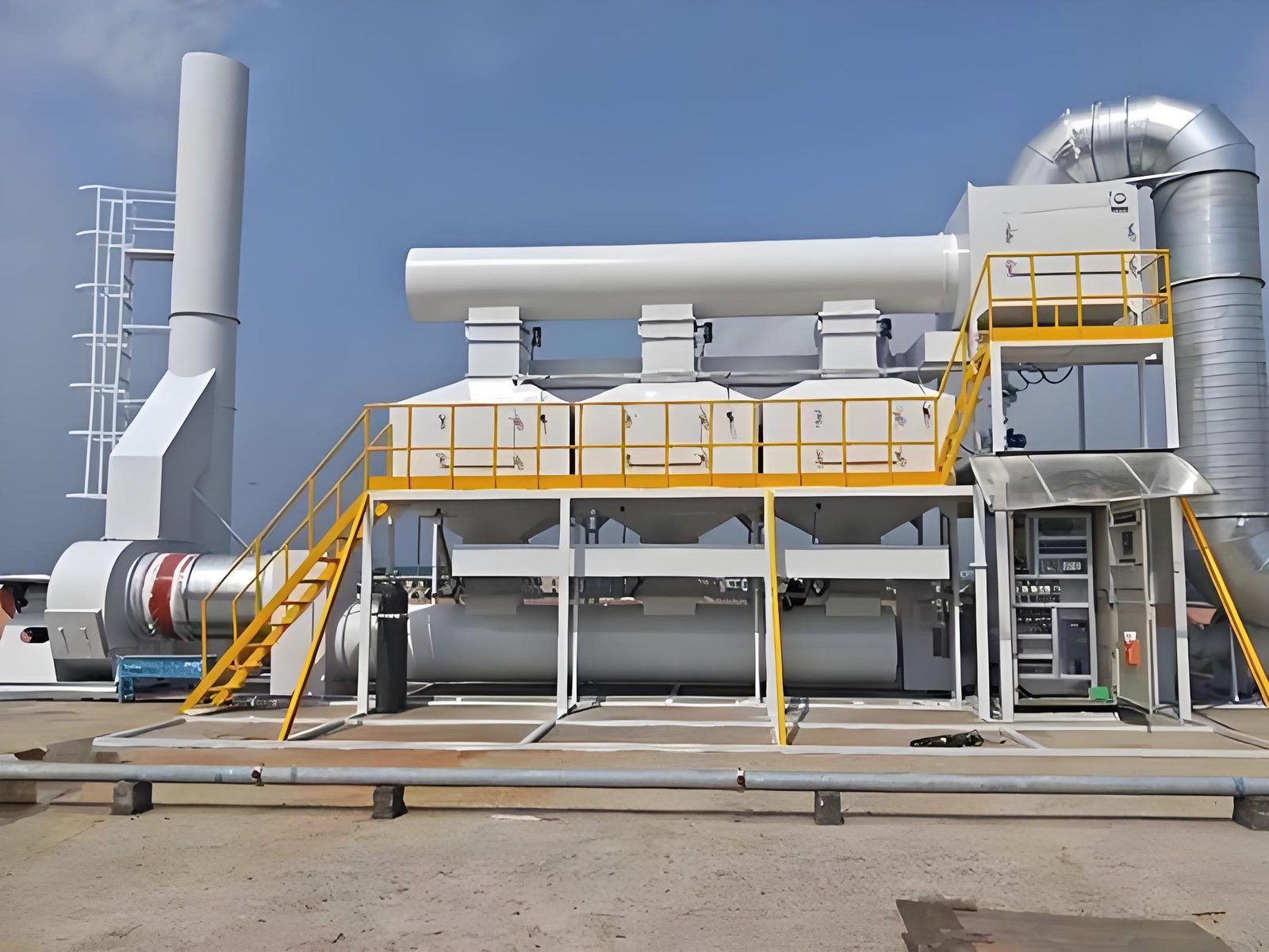
1. Map where the gas can cross its dew point
Begin with a source-to-rotor temperature and moisture map. Include permanent headers, temporary branches, cleaning exhaust, fresh-air inlets, outdoor duct runs and any section that can be isolated while another remains cold. Mark insulation, heat tracing, expansion joints, drains, access doors, filters, dampers and instruments on the same drawing.
For every segment, record the operating case rather than one nominal value:
- normal production, batch change and seasonal low-load operation;
- startup after an overnight or planned outage;
- shutdown, fan trip, damper isolation and restart;
- water-based cleaning, solvent purge or a wet maintenance task;
- humid ambient air entering through a bypass or open access point.
The design question is not simply “What is the inlet temperature?” It is “Which segment can become colder than the gas dew point, and how would collected liquid travel from there to the rotor?”
2. Separate humidity, condensable VOC and liquid carryover
Water condensation is only one moisture mechanism. A process stream can also contain condensable VOC, oil aerosol or a cleaning chemical that changes the effective risk. Ask the process owner to identify material families, concentration changes and credible upset cases. The answer should distinguish vapor, aerosol and liquid, because each follows a different control path.
| Risk form | Where it may appear | Evidence to request | Control owner |
|---|---|---|---|
| Humid air | Outdoor intake, wash or purge step | Temperature/RH or dew-point record by operating case | Process and controls team |
| Condensable vapor | Cooled duct, fan inlet, low point | Temperature profile and condensate observation method | Mechanical/process engineering |
| Liquid carryover | Mist eliminator, drain or failed separator | Drain path, inspection record and re-entrainment review | Pretreatment owner |
| Wet filter media | Cold filter housing or idle section | Housing temperature, DP trend and change-out inspection | Maintenance team |
Do not convert an unknown solvent or VOC mixture into a made-up water dew point. Ask the responsible process and equipment specialists to define the appropriate property data and safety controls.
3. Define the cold-start release gate
A burner light-off or fan start does not automatically make the rotor path ready. Define a release sequence that proves the relevant duct, filter, drain and rotor-inlet sections have reached their approved condition. The release gate should identify the instrument tag, the reading, the hold time if required by the OEM, and the person who can authorize process-gas admission.
At minimum, the checklist should cover:
- fan and damper status, including any bypass or recirculation path;
- temperature and humidity/dew-point readings at the coldest credible section;
- filter and mist-control differential pressure compared with its clean baseline;
- drain pots, traps and low points checked for blockage or accumulated liquid;
- rotor-inlet access or inspection evidence where the design permits it;
- alarms, interlocks and historian trends available for the first production case.
If the design cannot measure the coldest section directly, document the engineering basis for the proxy measurement. A single warm reading near the oxidizer does not clear a cold outdoor duct upstream.
4. Instrument the boundary, not just the machine
Instrumentation should answer the failure question. A sensor located after a heated section may show an acceptable temperature while a low point upstream is condensing. Place or specify measurements around the likely transition points: outdoor runs, fan suction, filters, mist eliminators, drains and the rotor inlet.
Use a traceable log that includes:
- instrument tag, location and calibration or verification status;
- gas temperature, ambient temperature and humidity/dew point where applicable;
- airflow or fan speed at the time of each reading;
- startup elapsed time and whether process gas was admitted;
- drain, filter and inspection observations;
- alarm or action threshold defined by the responsible engineer.
Trend data is especially important after a fan trip or a long idle period. Record the recovery path, not only the final value. A temperature that eventually recovers may still have allowed liquid to form during the transient.
5. Control drains and re-entrainment paths
Condensation control is incomplete if collected liquid cannot leave the system in a controlled way. Review low points, drain legs, traps, collection vessels, heat tracing where applicable and access-panel seals. Confirm that a blocked or full vessel cannot push liquid back into the gas path when the fan ramps.
Look for these re-entrainment mechanisms:
- a drain leg without a suitable seal or collection arrangement;
- poor slope or a pocket that stays wet after the fan stops;
- fan transients that disturb settled liquid;
- a cold flange, gasket or access door that admits humid air;
- a maintenance panel opened while the downstream section is warm and drawing air.
Inspection notes should identify location and operating context. Water at a low point does not by itself prove rotor damage, but it is evidence that the path and release logic need review before production resumes.
6. Review abnormal and seasonal cases
The dew-point boundary must survive more than the design steady state. Ask what happens when production starts in winter, when ambient humidity rises, when a source is isolated, or when a fan trips and restarts. The supplier and plant team should agree which cases are included in the design basis and which require an operator hold point.
| Case | Verify | Record before release |
|---|---|---|
| Cold morning startup | Coldest section warms without crossing the approved margin | Time-stamped temperature/RH trend and hold-point sign-off |
| Fan trip | Drainage, damper position and rotor protection logic | Alarm sequence, trip time and restart authorization |
| Wet cleaning or purge | Isolation prevents moisture migration to the rotor | Work permit, isolation proof and dry-out evidence |
| Seasonal high humidity | Controls remain valid at the site ambient condition | Ambient basis, set points and operator response |
| Low-load operation | Fan and heater control do not create a cold pocket | Airflow, heater state and rotor-inlet trend |
Avoid a generic statement such as “the system is protected from condensation.” Request the boundary, the case, the measurement and the release decision.
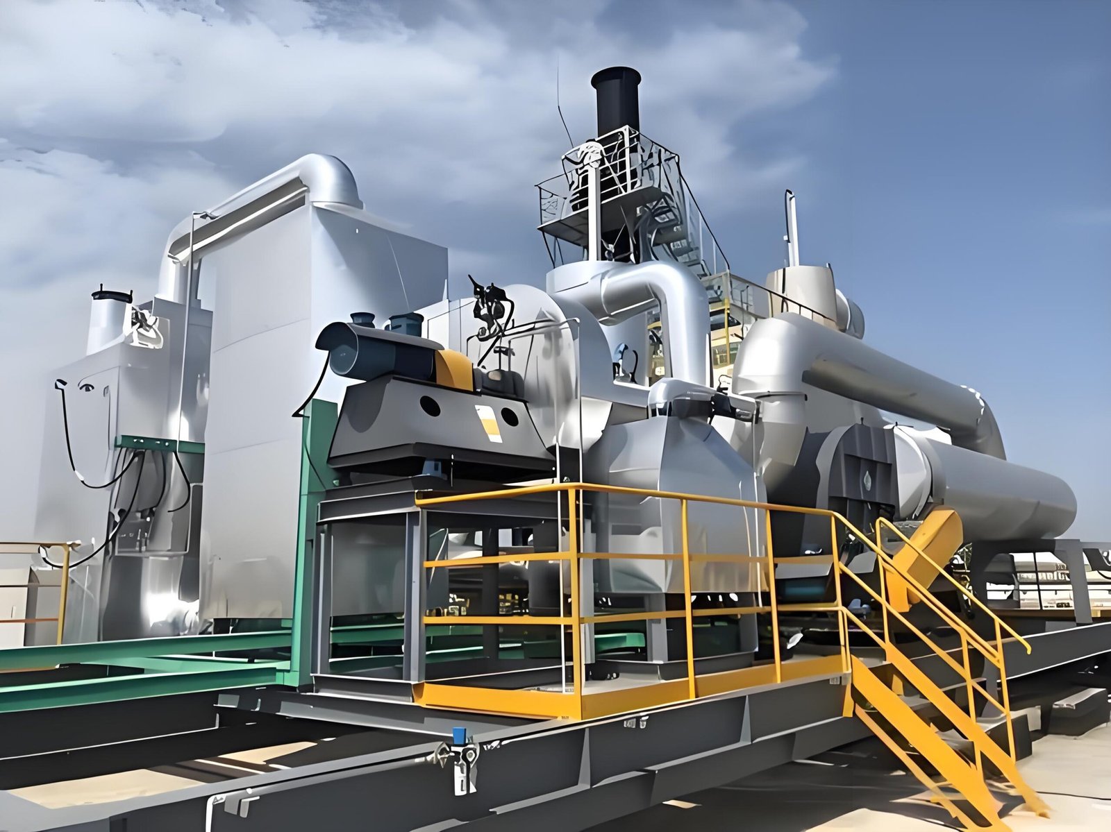
7. Normalize supplier scope and ownership
Condensation risk often sits between package boundaries. One supplier may show the rotor and heater, another the fan and duct, while the plant owns drains, insulation, heat tracing and the startup procedure. Put these interfaces into a buyer-controlled matrix before comparing proposals.
| Interface | Clarify in the proposal | Evidence at handover |
|---|---|---|
| Duct insulation/heat tracing | Included length, design basis and control responsibility | As-built route, test record and control narrative |
| Drains and collection | Equipment, seal, freeze/overflow provisions | Inspection access and drain test record |
| Dew-point measurement | Tags, locations, ranges and alarm ownership | Calibration/verification record and trend screen |
| Startup logic | Hold points, permissives and bypass behavior | Cause-and-effect, procedure and signed trial |
| Process change control | Who reviews a new wet or condensable source | MOC form and updated source map |