 Request Proposal
Rotor RTO Shutdown Preparation: Protect the Zeolite Concentrator Before a Planned Outage
A zeolite rotor concentrator changes the shutdown question. A conventional oxidizer can be taken offline after its approved purge and cooldown sequence, but the rotor section also contains adsorbent media, seals, bearings, purge air paths and a housing where dust or condensate can accumulate. If the process exhaust is isolated too early, humid air or residual solvent can remain where the next startup depends on stable adsorption and desorption.
This guide is for a planned production outage—not an emergency trip. The exact sequence must follow the equipment supplier’s instructions, the plant permit-to-work system and the site’s lockout/tagout (LOTO) procedure. The objective is simple: leave the rotor dry enough, clean enough, mechanically supported and fully documented for a controlled restart.
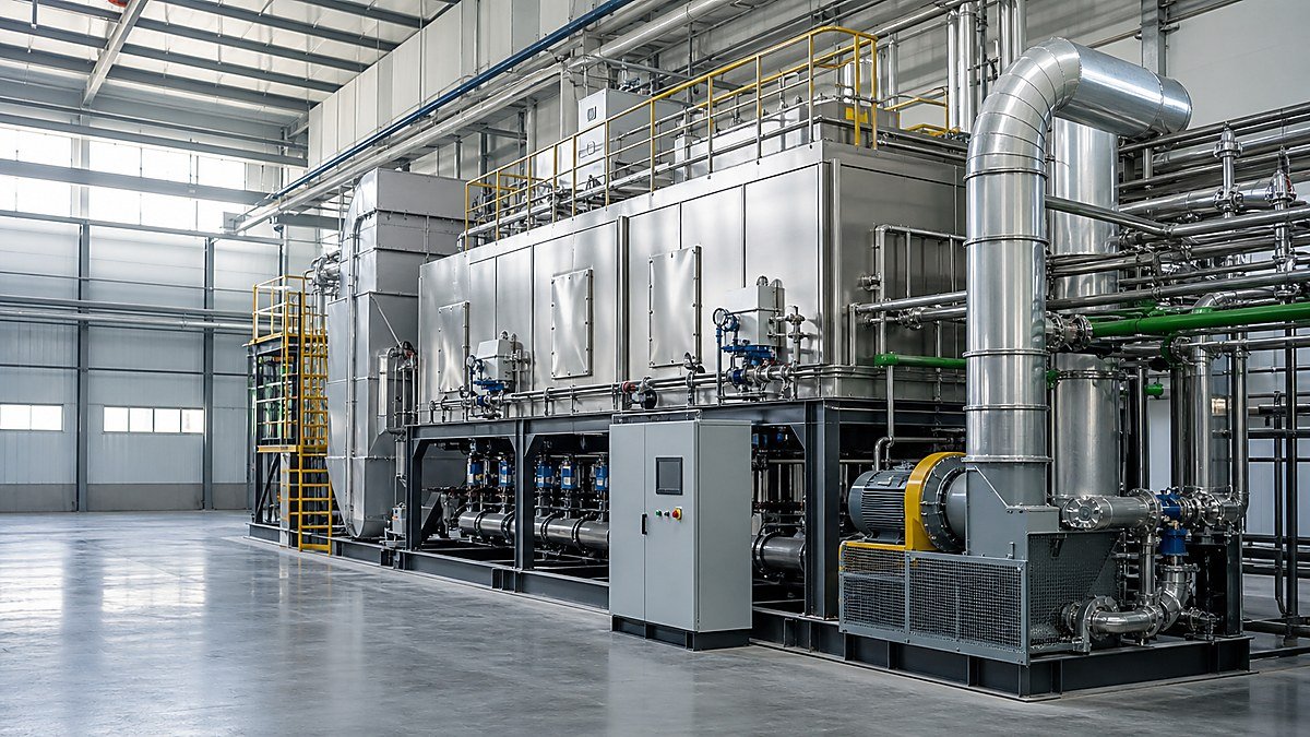
1. Define the outage case before touching a valve
“Shutdown” can mean a lunch break, a weekend, a multi-week maintenance outage or a process change while the VOC system remains electrically live. Those cases do not have the same risk. Write the intended state in a one-page outage sheet and have operations, maintenance, EHS and the system owner sign it.
Record the boundary conditions
Capture the last stable operating case and the planned isolation points:
- production lines connected to the rotor and which ones will remain active;
- expected duration and ambient temperature/humidity range;
- VOC family, dust/mist exposure and any upstream wet scrubber or condenser status;
- rotor inlet/outlet temperature, purge temperature, fan status and differential pressure;
- alarm, interlock or bypass status at the moment of handover;
- energy sources to isolate: electrical, thermal, pneumatic, fan inertia and stored pressure.
Do not infer that a closed process damper is a verified isolation. Identify the damper tag, its fail position, the proof method and the person responsible for checking it. If another exhaust source can backflow through a common header, include that path in the boundary review.
2. Finish the clean-air and solvent-displacement phase
Before process gas is removed, the rotor should complete the supplier-approved adsorption/desorption cycle at the specified clean-air flow. The purpose is to displace residual VOC vapour from accessible ductwork and reduce the load held in the rotor and downstream oxidation section. A clean-air purge is not a substitute for LEL controls, gas testing or an approved emergency procedure.
Use a written hold point rather than a timer alone. Operations should confirm:
- process exhaust has stopped or has been diverted to the approved route;
- clean-air purge fan and damper feedback agree with the command;
- temperature and differential-pressure readings are stable enough to compare with the last normal case;
- no high VOC, high temperature, bearing, seal or fan alarm is active;
- the permit issuer has accepted the measured atmosphere and isolation plan.
If the rotor is still receiving a variable solvent load, extending the purge may be safer than beginning mechanical work. Record the actual flow indication and the sample time; “fan on” by itself is not evidence of adequate displacement.
3. Control moisture, condensation and dust
Moisture is a shutdown risk because a cool rotor housing can reach dew point while the plant is idle. Water can carry soluble contaminants into the adsorbent, promote corrosion at metal interfaces or freeze in cold climates. Dust and sticky mist can also become harder to remove after a long idle period.
Make the dew-point decision explicit
Compare the expected metal temperature with the local dew point during the outage. Where the design permits, keep a dry, filtered air sweep or approved low-flow ventilation until the housing is below the specified safe condition. Where it does not, isolate and seal the housing exactly as the supplier requires. Never improvise a heater or bypass around a safety interlock.
Check the complete moisture path:
| Check | Evidence to keep | Why it matters |
|---|---|---|
| Upstream drain, demister or scrubber | Drain status, inspection note, last clean-out | Prevents liquid carryover into the rotor |
| Low points in ductwork | Photo or signed walkdown | Finds trapped condensate before isolation |
| Housing access doors and gaskets | Door/bolt condition and seal observation | Limits humid-air ingress |
| Instrument-air quality | Pressure and dew-point record if available | Protects pneumatic dampers and seals |
| Filter and mist-eliminator condition | Differential pressure and visual check | Reduces dust loading during restart |
If a plant has no reliable dew-point measurement, state that limitation in the outage record and use the conservative procedure approved for the equipment. Do not turn an estimate into a guarantee.
4. Cool down in a way that protects seals and bearings
Rotor RTO equipment contains hot surfaces and rotating hardware that respond differently to a fast stop and a controlled cooldown. Follow the approved ramp and minimum lubrication/turning requirements. A bearing can be stationary while the housing is still thermally expanding; a seal can appear normal at ambient temperature yet rub when the rotor is restarted.
Record at least:
- rotor-drive status, speed or turning-device status;
- bearing temperature and any vibration indication;
- rotor housing temperature at the supplier-defined points;
- purge-air temperature and fan/damper feedback;
- differential pressure across the rotor and key filters;
- the time each hold point was reached.
Do not open inspection doors until the permit confirms the surface temperature and atmosphere are safe. If the drive must rotate intermittently during a long outage, document the interval, lubrication requirement and responsible person instead of leaving it as an informal shift task.
5. Isolate energy and prove the mechanical state
The LOTO plan should match the actual equipment boundary. Typical sources include the rotor motor and heater, process and purge fans, compressed air, pneumatic actuators, hot-gas paths and gravity or stored pressure in ductwork. Each isolation needs a tag, lock owner and proof test.
After isolation, verify the mechanical state without defeating protection:
- damper position indication agrees with the field position;
- fan coast-down is complete and backflow paths are controlled;
- actuator air is isolated and residual pressure relieved;
- rotor drive cannot start from a remote or automatic command;
- access doors, drains and inspection ports are secured for the outage condition.
The existing RTO Shutdown and Restart Checklist gives a broader oxidizer sequence. Use this rotor-specific guide as an addendum, not as permission to replace the site’s approved LOTO or emergency instructions.
6. Create an inspection baseline before the outage grows
The best outage record is a comparison set. Photograph the rotor housing, access seals, drain points, filter faces, fan inlet and visible ductwork under the same lighting and angle used for previous inspections. Save instrument trends—not only a screenshot of the final value.
Flag deviations that need an owner and a decision date:
- rising rotor differential pressure;
- visible dust, oil mist or liquid staining;
- seal rub marks, unusual noise or drive vibration;
- unexplained temperature imbalance between rotor sectors;
- damaged insulation, loose lagging or corroded fasteners;
- a damper that reaches command but lacks position proof.
If cleaning or media work is proposed, define the acceptance evidence before work starts: photos, measured pressure drop, seal clearance check, bearing condition, filter replacement record and a signed restart release. This prevents a “looks clean” handover from becoming an untraceable change.
7. Plan the restart gate while the plant is still online
Restart readiness should be a gate with named sign-offs. Before process gas is re-admitted, confirm the rotor is reassembled, drains are closed or routed, filters are installed, instruments are calibrated or clearly tagged for verification, and all temporary blinds or covers are controlled. Restore utilities in the approved order and prove the automatic sequence in clean air first where required.
The first process run should use a defined operating case. Record flow, temperature, rotor speed, purge ratio or flow indication, differential pressure, fan load and outlet-monitor status. Compare the result with the pre-outage baseline; a new normal should not be declared until deviations are explained. The RTO Post-Restart Baseline Data article provides a compatible recording framework.
Suggested release matrix
| Gate | Minimum evidence | Owner |
|---|---|---|
| Mechanical complete | Work pack closed, doors/gaskets checked, guards fitted | Maintenance |
| Dry and clean | Drain status, filter record, moisture decision documented | Operations / EHS |
| Controls ready | Interlocks tested, damper feedback proven, alarms acknowledged | Controls |
| Utilities stable | Power, instrument air and fans available at approved condition | Operations |
| Clean-air run accepted | Sequence completes without abnormal temperature, DP or vibration | System owner |
| Process gas release | Defined case, trend capture and escalation contacts ready | Operations / EHS |
FAQ
Can a rotor RTO be left full of ambient air during a long outage?
Only if that state is explicitly allowed by the equipment supplier and the site’s moisture-control assessment. Ambient air may be acceptable in one climate and risky in another. Use dew point, housing temperature, contamination risk and the approved sealing or dry-air procedure to make the decision.
Should the rotor keep turning after process exhaust is isolated?
That depends on the drive, bearing and preservation design. Some systems require controlled turning or a turning gear; others require a defined stationary condition. Follow the supplier’s interval and lubrication instructions and record who owns the task.
Is a clean-air purge enough to declare the system gas-free?
No. Purge completion is one operating hold point. Gas testing, LEL controls, permit authorization and LOTO proof remain mandatory according to the site procedure.
What if differential pressure is higher after restart?
Stop and compare the trend with the pre-outage baseline. Check filter installation, damper position, condensate, dust carryover and seal condition before changing fan settings. A higher reading is a symptom to investigate, not a reason to claim a new design value.
What information should a buyer request from an integrator?
Request the rotor-specific shutdown and preservation sequence, boundary and isolation drawing, moisture/dew-point assumptions, turning-gear or lubrication requirements, inspection points, restart release matrix and the data fields to be trended. These documents show whether the proposed system can be operated and maintained, not only purchased.
A practical next step for plant teams
Before the next planned outage, assemble one evidence pack: last stable trends, the rotor and duct isolation drawing, dew-point or humidity information, filter and drain condition, LOTO boundary, inspection photographs and the restart release matrix. SERNO can review that pack with the exhaust-source list and help identify which rotor RTO operating cases need confirmation before a proposal or outage plan is finalized. Equipment selection and any site-specific sequence should remain subject to verified process data and the responsible engineer’s approval.