 Request Proposal
RTO Shutdown and Restart Checklist: Preserve Equipment, Verify Readiness
SEO title
RTO Shutdown and Restart Checklist: Preserve Equipment, Verify Readiness
Meta description
Plan a controlled RTO shutdown and restart with a practical checklist for isolation, preservation, inspections, controls, burner checks, process admission, and records.
Slug
`rto-shutdown-restart-checklist`
Excerpt
A planned RTO outage is not complete when the burner is off. This engineering checklist helps plant teams preserve the system while idle, inspect the gas path and safeguards, and restart in a controlled sequence before process exhaust is admitted.
Introduction
An RTO may be shut down for a production holiday, a planned maintenance window, a process change, or a utility outage. Turning off the burner is only one part of that event. The unit, duct network, induced-draft fan, valves, instruments, controls, and connected production sources can all be affected while the system is idle.
The return to service deserves the same discipline. A stable cabinet indication or a successful burner light-off does not by itself prove that the complete exhaust-treatment train is ready for process gas. Water ingress, condensation, a valve left isolated, an unbalanced damper, an instrument that has drifted, or a changed process solvent can alter the conditions assumed when the RTO was last operating.
This article provides a practical framework for a planned shutdown and restart. It is not a substitute for the installed system’s operating manual, site permit, lockout/tagout procedure, or a qualified safety review. Use the OEM documentation and site procedures as the controlling documents, then adapt the checklist to the actual RTO configuration and process hazards.
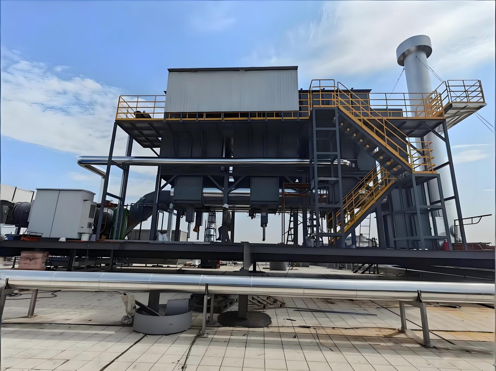
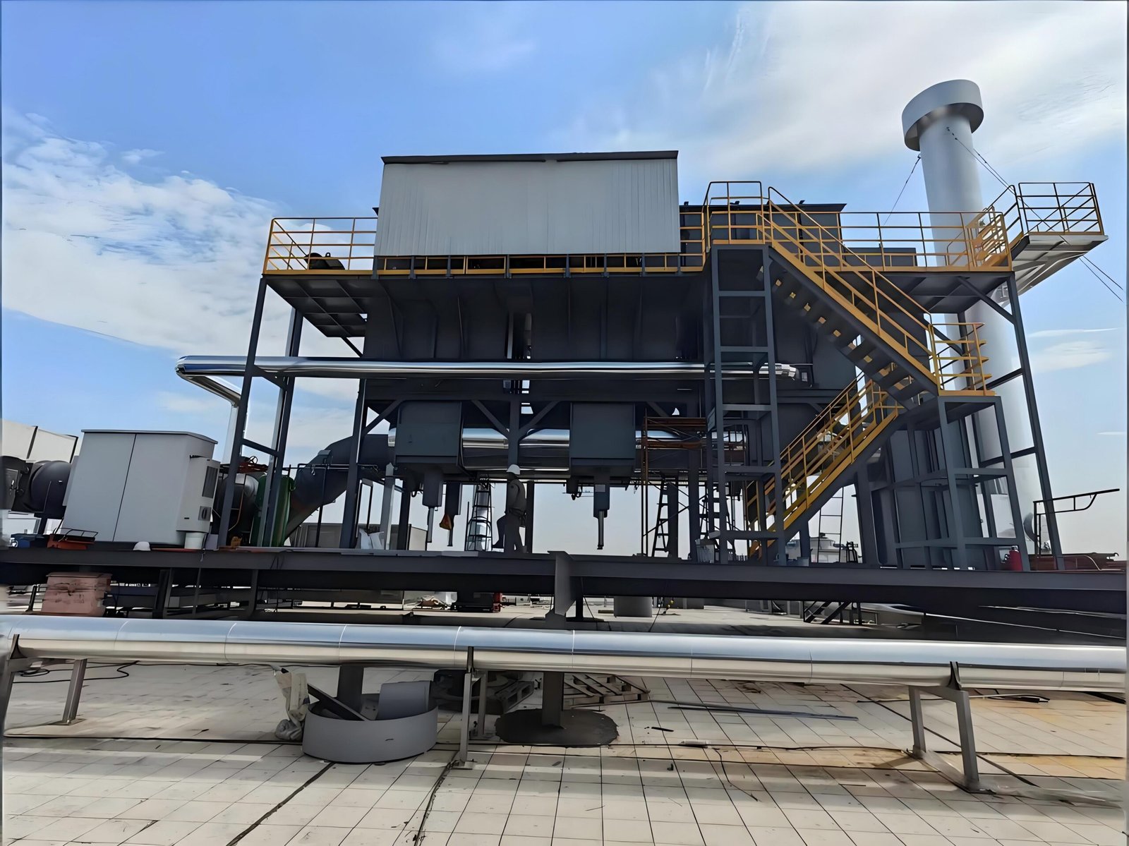
1. Define the outage boundary before the final process stop
Start with a short outage plan that states why the RTO will be stopped, how long it is expected to remain idle, which process sources will be isolated, and who owns each release decision. Treat the RTO as a train, not a single box. The boundary may include hoods, branch ducts, dampers, pretreatment, fans, the oxidizer, heat recovery, stack equipment, fuel supply, compressed air, electrical panels, drains, and monitoring points.
Record the last stable operating conditions before shutdown. Useful evidence commonly includes airflow, pressure drop, relevant temperatures, fan speed or damper position, burner status, valve-cycle status, alarm history, fuel indication where available, and the active process combination. These values are a baseline for restart investigation; they are not universal performance targets.
The plan should also identify credible changes during the outage. A new product, altered production schedule, duct modification, solvent change, or maintenance action can turn a routine restart into a management-of-change review.
Shutdown planning questions
- Which sources must be empty, purged, or isolated before the exhaust train is taken offline?
- What energy sources, stored pressure, hot surfaces, and moving equipment require site lockout/tagout controls?
- Which valves, dampers, drains, access doors, and temporary blanks must have a positive position record?
- What condition needs protection during a short idle period versus a long or humid-season shutdown?
2. Shut down in a controlled sequence and preserve evidence
Follow the installed operating sequence and plant safety procedure. In many configurations, the process exhaust is removed first, the unit completes its specified purge or cool-down behavior, and utilities are isolated only when the system documentation permits it. Do not infer a safe sequence from a different RTO model: chamber arrangement, valve configuration, controls, upstream process, and local safeguards matter.
Before releasing the equipment, document the final configuration. A simple signed status sheet can capture isolation points, damper positions, access-door status, temporary work controls, open maintenance items, and the person responsible for removal of each lock or tag. Photographs may help local teams, but they should support rather than replace a controlled isolation register.
Avoid leaving a vague instruction such as “restart after holiday.” The next shift needs to know what was intentionally changed, what was found, and what has not yet been verified.
3. Protect the idle RTO from water, contamination, and unintended movement
Idle equipment can degrade quietly. Inspect weather protection and drain paths around roofs, ducts, stacks, fan housings, access covers, and low points. Water or condensation can affect insulation, corrode ductwork, foul instrumentation, damage electrical components, and create difficult-to-explain behavior during the next heat-up.
Preservation actions should be based on outage duration and site conditions. Depending on the installed configuration and OEM instructions, they may include securing access covers, protecting open ductwork during maintenance, managing drains, preventing dust ingress, maintaining specified enclosure conditions, and protecting control equipment from moisture. Do not seal a system in a way that defeats a required vent, creates a trapped hazard, or conflicts with site safety procedures.
Check for contamination introduced by adjacent work. Welding debris, blasting media, insulation fibers, overspray, cleaning chemicals, or unsecured tools can create restrictions or safety concerns in the gas path. If process dust, mist, silicone-containing materials, halogens, sulfur compounds, or other contaminants are relevant, the inspection scope should reflect the actual risk to ceramic media, catalyst where installed, instruments, and downstream equipment.
4. Inspect the gas path, fan, valves, and access points before energizing
The restart inspection should trace the actual gas path from collection point to stack. Confirm that the work boundary has been cleared and that all covers, blanks, guards, expansion joints, flexible connections, supports, drains, and access doors are in their correct service condition. Review any maintenance records for changes to duct routing, damper settings, fan components, valve seals, or insulation.
Pay particular attention to items that change pressure balance or permit unintended air entry. An access door that is not seated, a damper left in a temporary position, a leaking valve, or an obstructed drain can affect operation even when the RTO reaches temperature normally. Where the system history includes pressure-drop or valve concerns, compare the post-restart readings with the pre-shutdown baseline and investigate meaningful differences rather than adjusting setpoints immediately.
| Area | Verify before restart | Why it matters |
|---|---|---|
| Collection and branch ducts | Isolation removed as planned; hoods and dampers returned to approved positions | Supports intended capture and airflow distribution |
| RTO chambers and media path | Access closed; no foreign material; maintenance work released | Avoids leakage, restrictions, and damage |
| Switching valves and actuators | Mechanical condition, air supply, feedback, and commanded movement checked per procedure | Valve position affects purge, heat balance, and gas routing |
| Fan and motor | Guards, rotation check method, vibration condition, electrical protection, and drain condition reviewed | The fan determines capture and system pressure |
| Stack and downstream equipment | Access, drainage, supports, heat recovery or polishing equipment checked where installed | Confirms the full discharge path is available |

5. Prove controls, interlocks, and combustion readiness without assuming
Before process gas is admitted, verify the control system according to the approved functional test procedure. Confirm that required instruments have power, plausible readings, correct tags, and current calibration or verification status where applicable. Review alarms, permissives, emergency-stop functions, fan proving, valve feedback, pressure switches, temperature signals, gas-train safety functions, and any concentration or LEL safeguards specified for the installation.
Combustion-system checks must follow the burner manufacturer’s instructions and be performed by personnel qualified for the task. A restart after fuel-system work, electrical work, a long shutdown, or an unexplained prior trip may require a more formal review. Do not bypass a permissive merely to obtain ignition. A bypass can hide the condition that should prevent a startup.
The objective is not to claim a particular destruction efficiency or fuel rate. It is to demonstrate that each safeguarding and control function needed for the approved operating envelope is available before the exhaust source is connected.
6. Restart in stages: equipment first, then controlled process admission
A staged restart separates mechanical and controls questions from process questions. First, complete the documented equipment-start sequence without process exhaust, as the installed procedure allows. Observe fan, valve, temperature, burner, pressure, and alarm behavior during the warm-up and initial cycles. Record the conditions and compare them with the prior stable baseline, allowing for documented differences in ambient temperature, production state, or maintenance changes.
Next, admit process exhaust in a controlled order. Start with the agreed source or low-risk operating case, then add sources only after the team confirms capture, pressure, temperatures, and safeguards remain acceptable. Avoid combining first restart, peak production, solvent changeover, and unfamiliar process conditions in the same moment. When the process profile has changed, pause for a qualified engineering and safety review rather than treating the event as a normal restart.
Practical staged-restart record
| Stage | What to record | Release criterion |
|---|---|---|
| Mechanical readiness | Work release, guards, access covers, utility availability | All listed shutdown controls cleared by the responsible owner |
| Controls and burner readiness | Permissive tests, signal plausibility, alarm status, combustion test result | Approved procedure completed with no unresolved safeguard issue |
| Warm-up and cycle observation | Temperature trend, valve operation, fan/pressure behavior, abnormal alarms | Behavior consistent with approved procedure and investigation of any deviation |
| First process admission | Source identity, operating state, airflow/pressure observations, relevant process information | Capture and RTO response remain within the agreed operating envelope |
| Return to routine operation | Final configuration, open items, baseline comparison, handover name/time | Responsible team accepts documented operating status |
7. Close the event with records that make the next decision easier
The most valuable restart record is usable at the next outage. Keep the shutdown sheet, work releases, inspection findings, maintenance changes, alarm notes, final operating observations, and unresolved items together. Note which readings are measured, estimated, or unavailable. This prevents a future team from treating a temporary workaround or unusual baseline as normal design intent.
If the restart exposed persistent pressure change, repeated valve alarms, unstable combustion, unexpected temperature behavior, or a process-source change, identify the follow-up owner and due date. A return to production is not evidence that the root cause has been resolved.
FAQ
How long can an RTO remain shut down?
There is no single answer. The acceptable idle period depends on the installed equipment, environment, preservation method, process contamination, and OEM/site requirements. Plan the preservation scope around those conditions rather than relying on a generic number of days.
Can we restart the RTO before checking the process ducts?
The RTO may be capable of warming up, but the complete exhaust train should be released through the approved procedure before process gas is admitted. Unreleased access points, changed dampers, water, or temporary work controls in the duct system can affect capture, pressure, or safety.
Should we change setpoints when readings differ after restart?
Not as the first response. Compare the difference with maintenance activity, ambient conditions, process state, instrument condition, and the pre-shutdown record. Determine the cause through the approved engineering process before changing a protective or operating setting.
What should an RTO buyer ask a supplier to provide?
Ask for the installed system’s shutdown, preservation, and restart guidance; functional-test requirements; list of required utilities and instruments; and the information needed to assess a future process or duct change. The final procedure must match the supplied configuration and site controls.
Conclusion
A planned RTO outage is a controlled change in operating state. Preserving the equipment, confirming the full gas path, testing safeguards, and admitting process exhaust in stages helps a plant separate normal restart behavior from a condition that needs investigation.
For a planned RTO project or an installed system facing a process change, SERNO can review the available exhaust data, operating scenarios, equipment scope, and documentation needs for a technical discussion. Any final operating, safety, and compliance decision must be made against the actual installation, applicable requirements, and qualified site procedures.
Internal-link and pre-publication notes
- Suggest contextual links to SERNO articles on RTO safety interlocks, valve leakage diagnosis, and ceramic-media fouling after their URLs are verified on the live site.
- Keep the canonical self-referencing. Do not add unverified local permit, performance, customer, certification, pricing, or energy-saving claims.