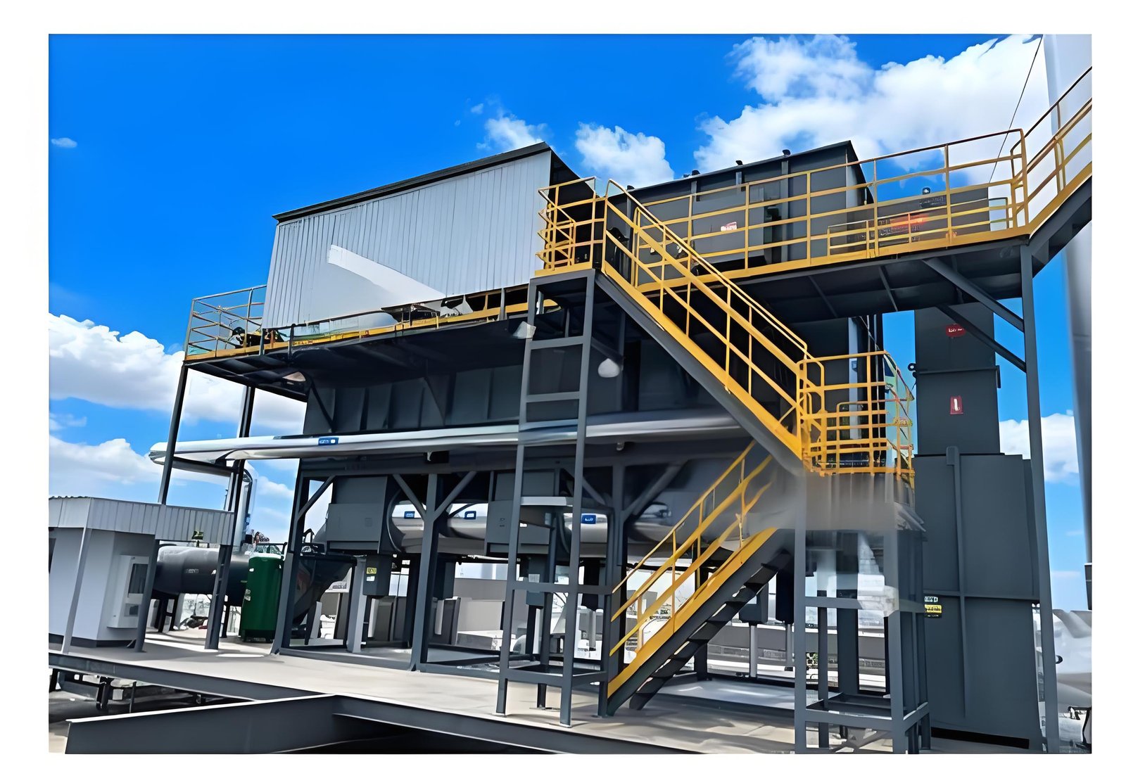
RTO Expansion Joint Inspection: Build a Repair Scope Before False Air Becomes a Reliability Problem
Expansion joints are small-looking components on a large exhaust system, but they sit at a difficult boundary: hot ductwork moves, supports carry load, insulation hides condition, and the joint must accommodate movement without becoming an unintended opening. A torn cover, displaced liner, loose flange, failed clamp, or overloaded support can allow air in or process gas out. The same observation can also be confused with a damper problem, fan-pressure change, sampling issue, or normal thermal movement.
For an RTO owner, the useful question is not “Does this joint look old?” It is: what evidence shows that the joint is outside its intended service condition, what risk does that create, and what repair boundary can a contractor quote and verify? This guide gives a field-review sequence. It does not replace the joint manufacturer’s design data, a site isolation procedure, or a local emissions and safety assessment.
1. Start with the movement and gas-path map
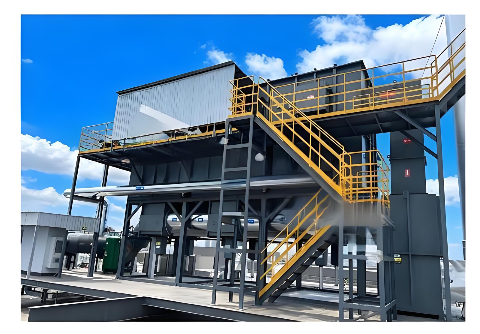
Before opening insulation or planning a replacement, mark every flexible connection on the current as-built drawing. Record whether the joint is on the hot-gas path, combustion-air path, purge path, bypass, or a utility connection. Note nearby fans, dampers, supports, guides, anchors, drains, access doors, insulation breaks, and sample points.
The map should answer four practical questions:
- Which components can move relative to each other during heat-up and cooldown?
- Which side is expected to see negative or positive pressure in each operating mode?
- Can a joint be isolated and inspected without opening the process boundary elsewhere?
- What downstream instrument or observation would change if air entered at this point?
Do not infer the pressure direction from a generic RTO diagram. Confirm it from the installed fan arrangement, operating sequence, and approved drawings.
2. Inspect the joint without turning a clue into a conclusion
Use the site’s permit, lockout, cool-down, and access controls first. A visual inspection can document condition without proving a leak. Photograph the joint from a repeatable angle and include a reference to the equipment tag or drawing grid, not a customer name or sensitive identifier.
Look for:
- cuts, pinholes, fraying, hardening, blistering, or heat discoloration on the cover;
- a displaced inner liner, exposed insulation, or a cover pulled off-center;
- loose, missing, or unevenly tightened fasteners and clamps;
- flange distortion, witness marks, rubbing, or contact with a support;
- compressed travel that leaves no movement allowance, or excessive extension;
- support, guide, or anchor changes that transfer load into the joint;
- moisture, dust tracks, or deposits that indicate a possible flow path.
These are condition observations. They become stronger evidence only when connected to the design movement range, temperature history, pressure condition, and a controlled inspection or test.
3. Compare as-found condition with thermal movement evidence
An expansion joint can appear to move during normal operation. The review should therefore compare the as-found position at defined operating states: cold, warm-up, stable production, and cooldown where safe and practical. Record the operating state, approximate time, nearby temperature readings, fan or damper state, and any maintenance work completed since the last baseline.
Avoid using a single photograph as a travel limit. If the joint has travel indicators, witness marks, or manufacturer-specified movement dimensions, record them against the approved drawing. If no reliable baseline exists, state that limitation and define a controlled baseline task rather than inventing an acceptance value.
4. Separate false-air clues from other RTO causes
Air ingress may change fan loading, pressure balance, temperature patterns, or apparent fuel demand. It is not the only explanation. A disciplined review compares the joint evidence with process load, airflow, damper position, valve sequence, analyzer quality, and recent maintenance.
| Observation | Possible explanations | Evidence to collect before a repair decision |
|---|---|---|
| Fuel demand rises while inlet VOC load is similar | Air ingress, lower heat recovery, changed airflow, sensor drift, or process variation | Comparable operating case, fuel trend, airflow/pressure data, temperature and calibration records |
| Dust or moisture track near a joint | Local leakage, washdown, condensation, insulation damage, or a nearby drain path | Direction of track, joint condition, weather/process history, isolation inspection |
| Duct pressure changes after maintenance | Joint or support disturbance, damper position, fan change, filter condition, or instrument error | Work pack, command/feedback trace, fan data, differential-pressure checks |
| Cover is frayed but no operating change is proven | Aging, rubbing, thermal fatigue, or an early leak path | Movement clearance, rub marks, liner condition, OEM repair criteria |
The goal is to preserve alternatives until the evidence supports a narrower conclusion.
5. Define the repair boundary a supplier can quote
“Replace the expansion joint” is rarely a complete scope. The purchase package should identify the joint tag, physical limits, drawing revision, dimensions to verify in the field, material and temperature basis from the OEM, access and lifting needs, isolation assumptions, and the disposition of adjacent insulation and supports.
Ask the supplier to state explicitly:
- whether the proposed work is a cover-only repair, liner repair, complete joint replacement, or a wider duct correction;
- which measurements are required before fabrication and who owns them;
- how adjacent guides, anchors, flanges, gaskets, and fasteners will be checked;
- what temporary protection is needed during hot work, lifting, or weather exposure;
- what inspection and leak-evidence records will be delivered at handover.
This keeps a small component from becoming an uncontrolled change to the gas path.
6. Plan isolation, access, and work quality before shutdown
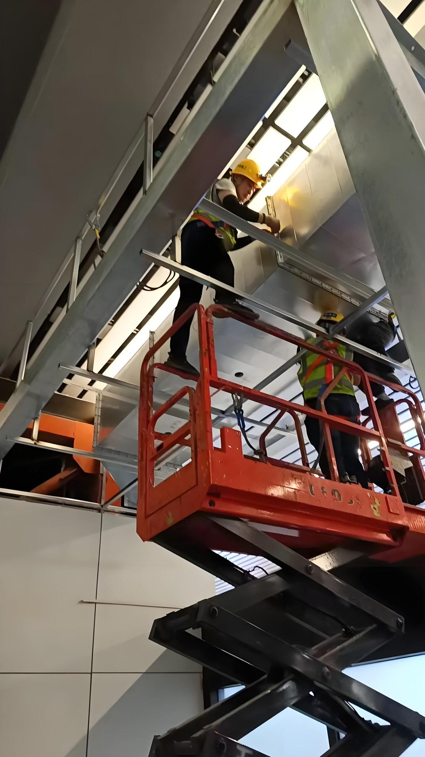
Expansion-joint work often depends more on access and isolation than on the fabric component itself. Confirm how the RTO will be placed in a safe state, how residual heat and process gas will be managed, and whether the work requires scaffolding, a crane, weather protection, or removal of cladding.
The work pack should include:
- isolation points and a positive confirmation method;
- cool-down, purge, gas-test, and confined-space requirements defined by the site;
- temporary support or load-transfer controls;
- protection of nearby sensors, insulation, cables, and coatings;
- dimensional checks before fabrication and after fit-up;
- fastener, gasket, liner, and cover inspection records;
- photographs of as-found, open, installed, and as-left conditions;
- a controlled return-to-service and observation plan.
The exact test method depends on the joint design and site procedure. Do not promise a pressure test, smoke test, or emissions result when the installed boundary or local safety rules do not support it.
7. Build an evidence pack for restart and future diagnosis
Close the loop with a small, searchable record. Include the tag and drawing reference, operating state, photographs, measured dimensions, material certificates if required by the approved scope, inspection sign-offs, deviations, and the date and person responsible for each observation.
After return to service, compare the same operating indicators used in the pre-work review. A stable result is useful evidence, but it does not prove that every possible leakage path is eliminated. If a VOC, pressure, temperature, or fuel trend remains abnormal, continue the isolation sequence rather than assigning the cause to the repaired joint by default.
Buyer checklist: questions before approving the repair
| Review item | Minimum question |
|---|---|
| Identification | Is the joint tag and drawing revision unambiguous? |
| Design basis | What movement, temperature, pressure, and material basis applies to this installed joint? |
| Condition | Which observations are documented as-found, and which are still hypotheses? |
| Interfaces | Are supports, guides, anchors, insulation, flanges, and nearby instruments inside or outside the scope? |
| Isolation | What safe-state, purge, cool-down, and access steps are required by the site? |
| Verification | What as-left inspection and controlled restart evidence will be delivered? |
| Change control | Will the repair alter duct geometry, support loads, or the approved operating sequence? |
FAQ
Can a frayed expansion-joint cover prove an RTO emissions problem?
No. It is a condition clue. Link it to pressure, temperature, operating-state, and inspection evidence before assigning it as the cause of an emissions observation.
Should every old expansion joint be replaced during an outage?
Not automatically. Review the installed design, movement history, visible condition, interfaces, and the consequences of opening the boundary. A documented inspection can support a repair, monitoring action, or replacement scope.
What information should be sent with an RFQ?
Send the joint tag, current drawings, photographs, dimensions to verify, operating temperature and pressure basis where approved for sharing, access constraints, isolation assumptions, and the inspection records expected at handover.
Does a repaired joint require a new RTO performance test?
The answer depends on the site change-control process and what the repair changes. Define the release evidence with the responsible engineering and EHS teams; do not assume a generic test is sufficient.
Practical CTA
If an RTO expansion joint is showing wear, dust tracking, movement concerns, or a suspected false-air path, prepare the drawing, photographs, operating states, and recent maintenance record before requesting a repair scope. SERNO can review the boundary with the relevant RTO, duct, fan, and pretreatment context and help define the information needed for a technically comparable quotation.