Author: serno_admin

  • What Are VOCs in Factory Exhaust? A First Check Before Choosing Treatment Equipment

    What Are VOCs in Factory Exhaust? A First Check Before Choosing Treatment Equipment

    What Are VOCs in Factory Exhaust? A First Check Before Choosing Treatment Equipment

    When a factory starts asking about exhaust-treatment equipment, the first question is often, “Do we need an RTO?” A better first question is simpler: what is leaving the process, and where is it being collected?

    VOCs, or volatile organic compounds, can become vapors during manufacturing. Possible sources include solvents, inks, coatings, adhesives, cleaning, resin handling, mixing, drying, curing, printing, and chemical processes. A smell is a reason to investigate, not a compliance conclusion.

    This guide is for factory owners and managers taking a first look at industrial VOC treatment. It is not a local legal opinion, a health assessment, a sampling plan, or a technology promise.
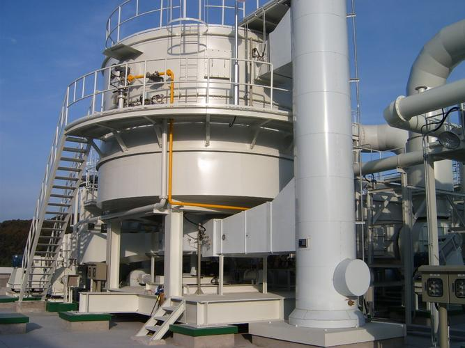
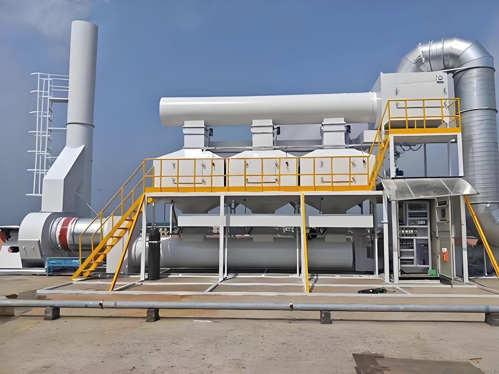
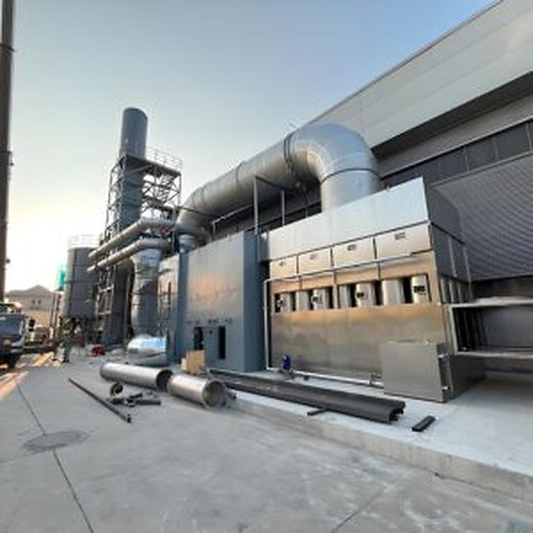
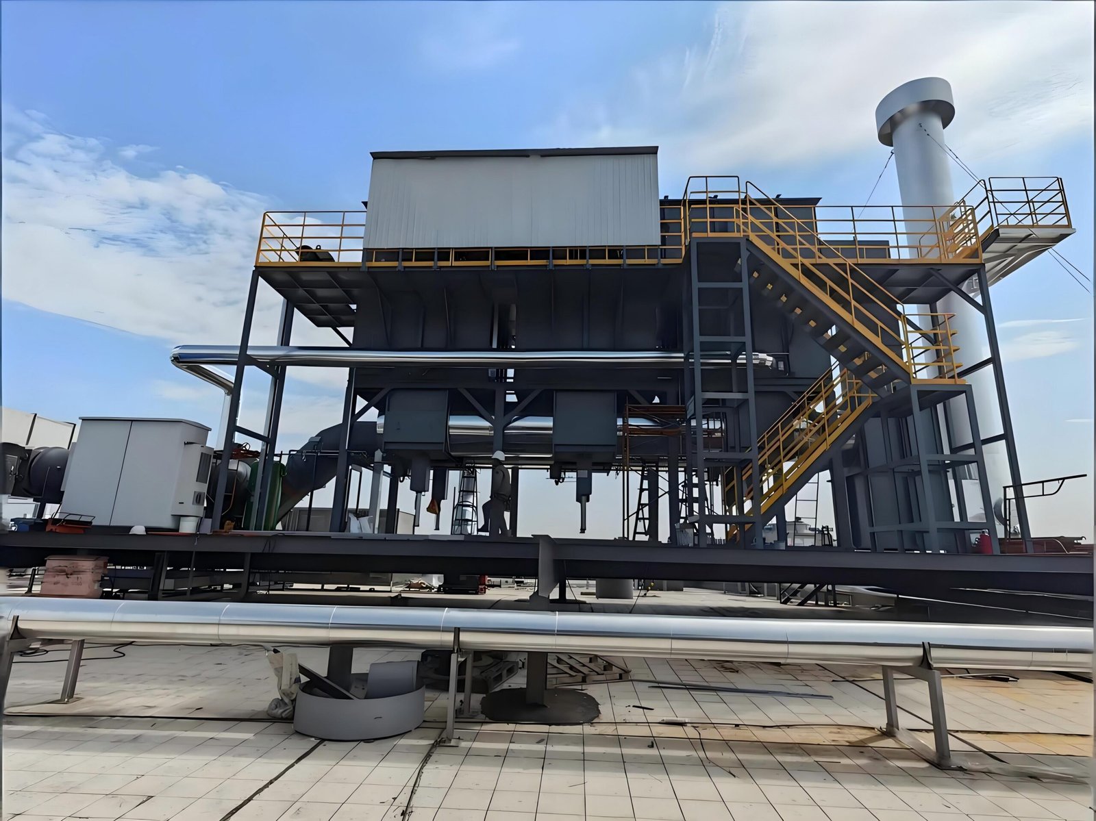
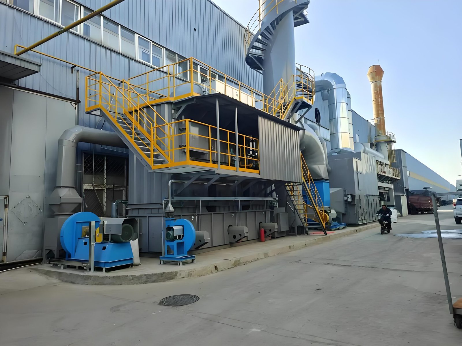
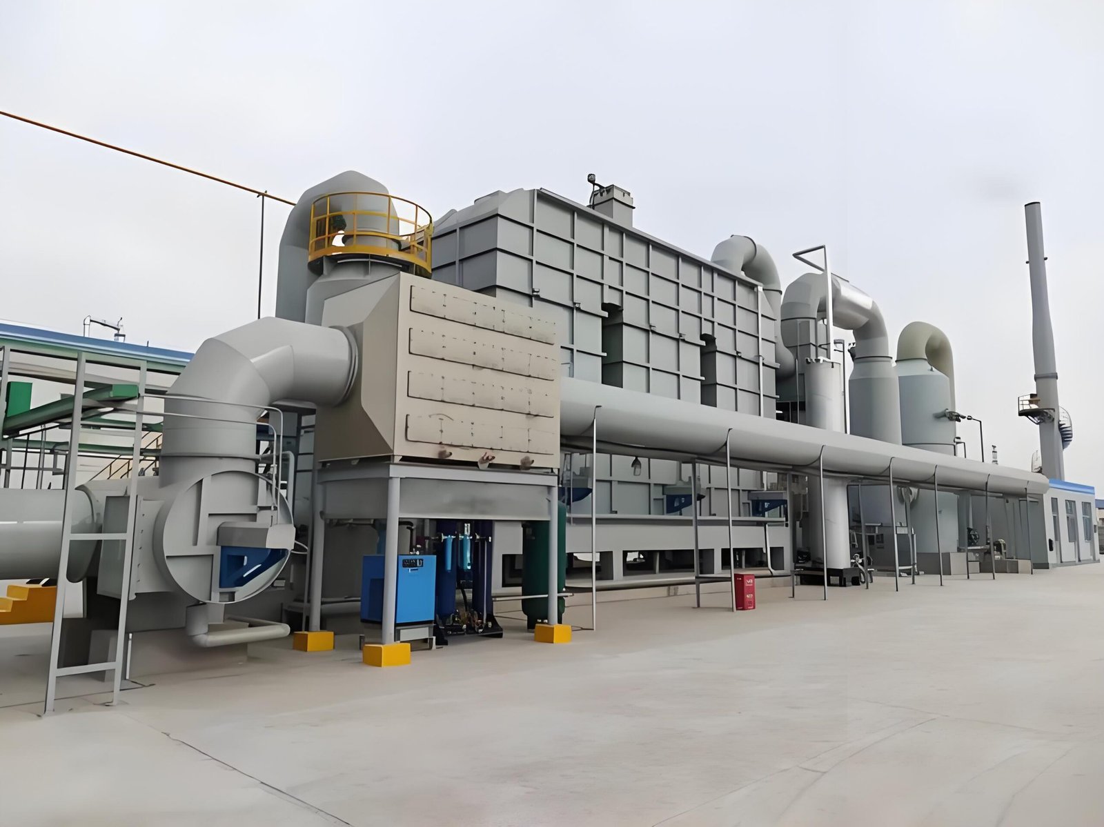
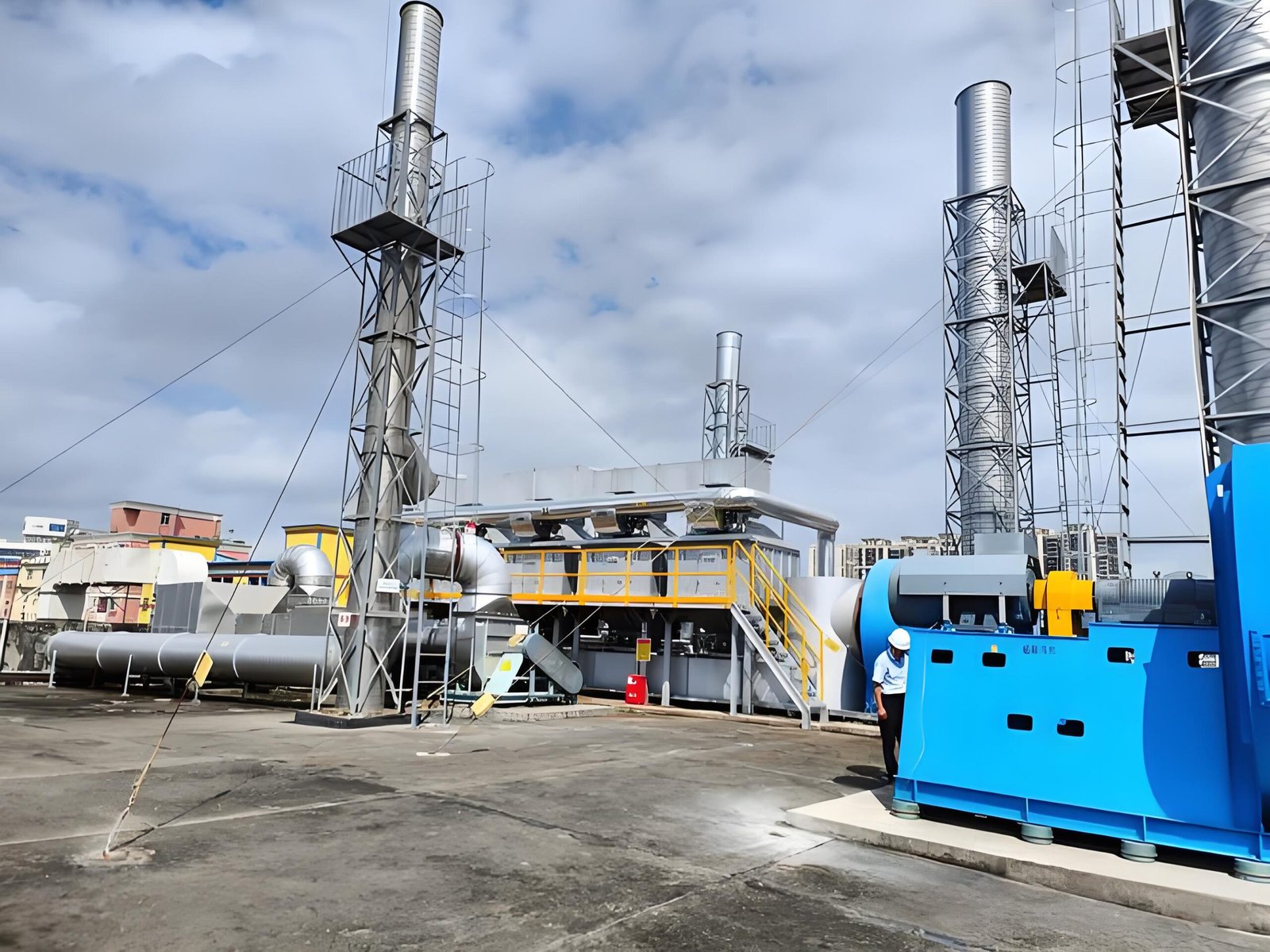
    Industrial VOC treatment equipment with connected ductwork in an outdoor plant installation

    Find the source and capture point

    VOCs are a category, not one gas. A factory exhaust stream may include one compound or a mixture, and can also contain moisture, particles, oil mist, or other components. The relevant details come from the actual materials, process, temperature, ventilation arrangement, and production schedule.

    Walk the production route from material opening to finished product. Look for when a liquid, ink, coating, adhesive, solvent, resin, or cleaning agent is exposed to air or heated.

    Common examples include:

    • spray booths, flash-off areas, and curing ovens;
    • printing presses, ink stations, dryers, and laminators;
    • adhesive application and drying sections;
    • solvent cleaning, wiping, and parts washing;
    • mixing, filling, dispensing, and storage venting; and
    • resin, composite, rubber, pharmaceutical, or chemical processing steps.

    This is a starting list, not an equipment conclusion. The site team should connect each suspected source to the materials actually used and the process conditions actually present. The U.S. EPA offers general VOC and ground-level ozone background; confirm site obligations with the applicable local authority and qualified advisers. Sources reviewed 2026-07-24: EPA VOC background and EPA ground-level ozone basics.

    The treatment unit is downstream. For each suspected source, ask: Is there a hood, enclosure, slot, canopy, oven connection, or duct branch? When does the fan run? Are other sources connected to the same duct?

    Poor capture cannot be corrected simply by choosing a larger downstream unit. A defined capture boundary gives a future review a clearer basis for judging ductwork, pretreatment, fan arrangement, and treatment options.

    Make a simple first inventory

    You do not need to solve the project during the first walk-through. Record what you can verify and leave unknown items marked as unknown.

    What to recordPractical questionWhy it helps
    Process stepWhat operation is taking place?Links exhaust to a real production activity.
    MaterialWhich coating, ink, adhesive, solvent, resin, or cleaner is used?Points to SDS and chemistry information.
    Capture pointWhere is the vapor collected or vented?Defines the possible treatment boundary.
    Operating patternContinuous, batch, intermittent, or seasonal?Helps compare suitable operating approaches.
    Existing controlsFan, duct, filter, carbon, scrubber, or no system?Avoids overlooking installed equipment and interfaces.
    ChangesNew material, line, product, or production rate?Helps explain why the question arose now.
    Local requirementWhich permit, standard, inspection item, or authority applies?Keeps the assessment tied to the actual jurisdiction.

    If available, include current SDS documents, a process/duct sketch, and a record of when each line operates. Formal sampling and regulatory interpretation should use appropriate qualified support where required.

    Do not mix dust, acid mist, and VOC vapors into one equipment decision

    Dust, acid or alkaline gas, oil mist, moisture, and organic vapors can need different collection, pretreatment, and control approaches. A process can contain more than one contaminant.

    For example, significant particulate or mist may need pretreatment before an oxidation system. The actual route must be based on the stream and installed process, not a generic product name.
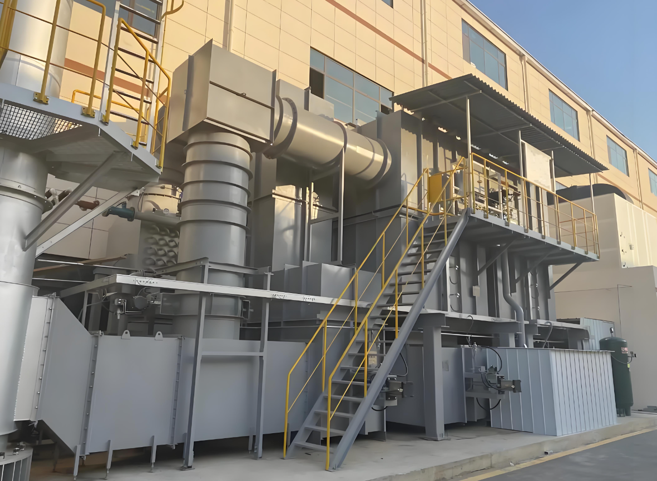
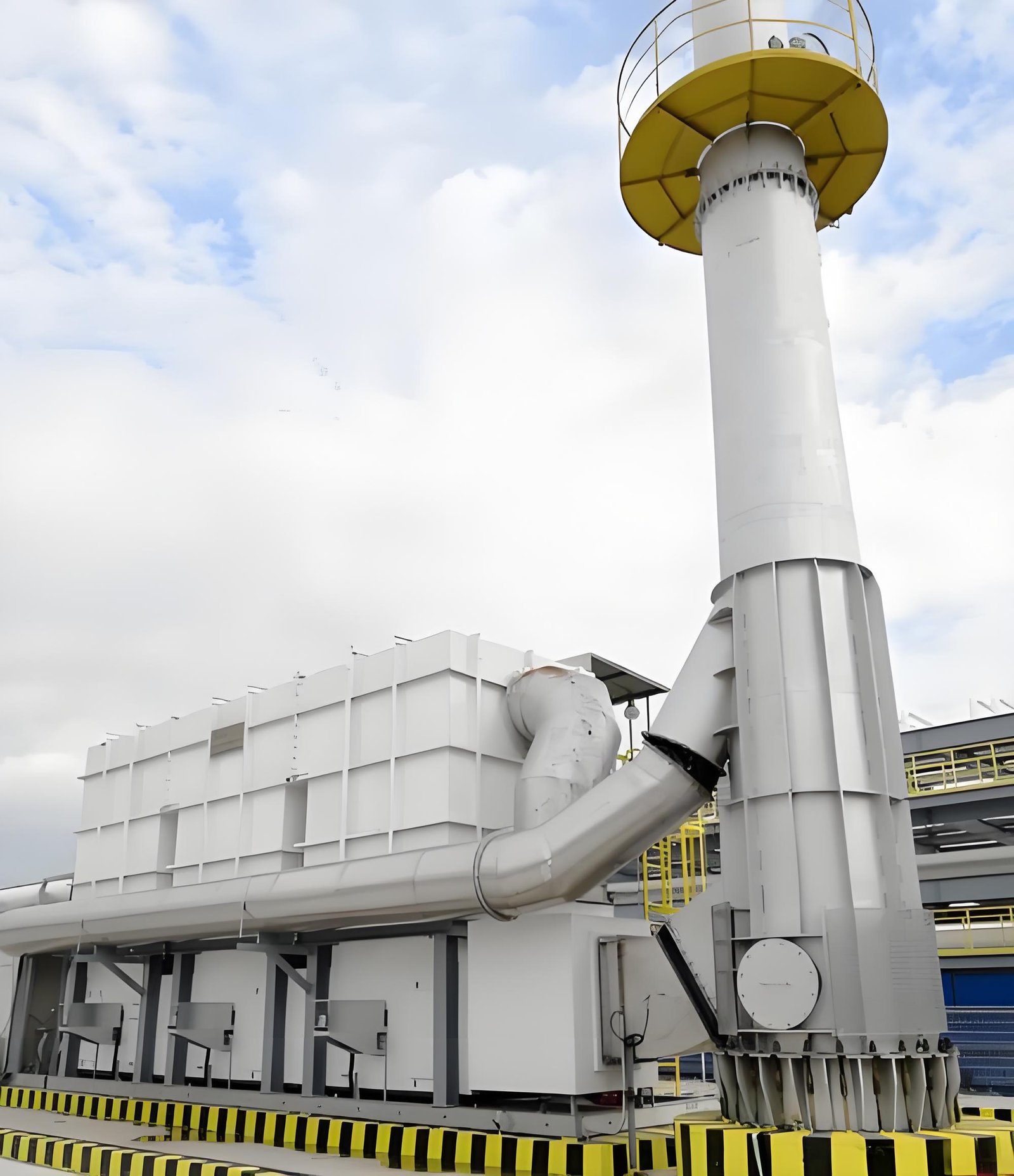
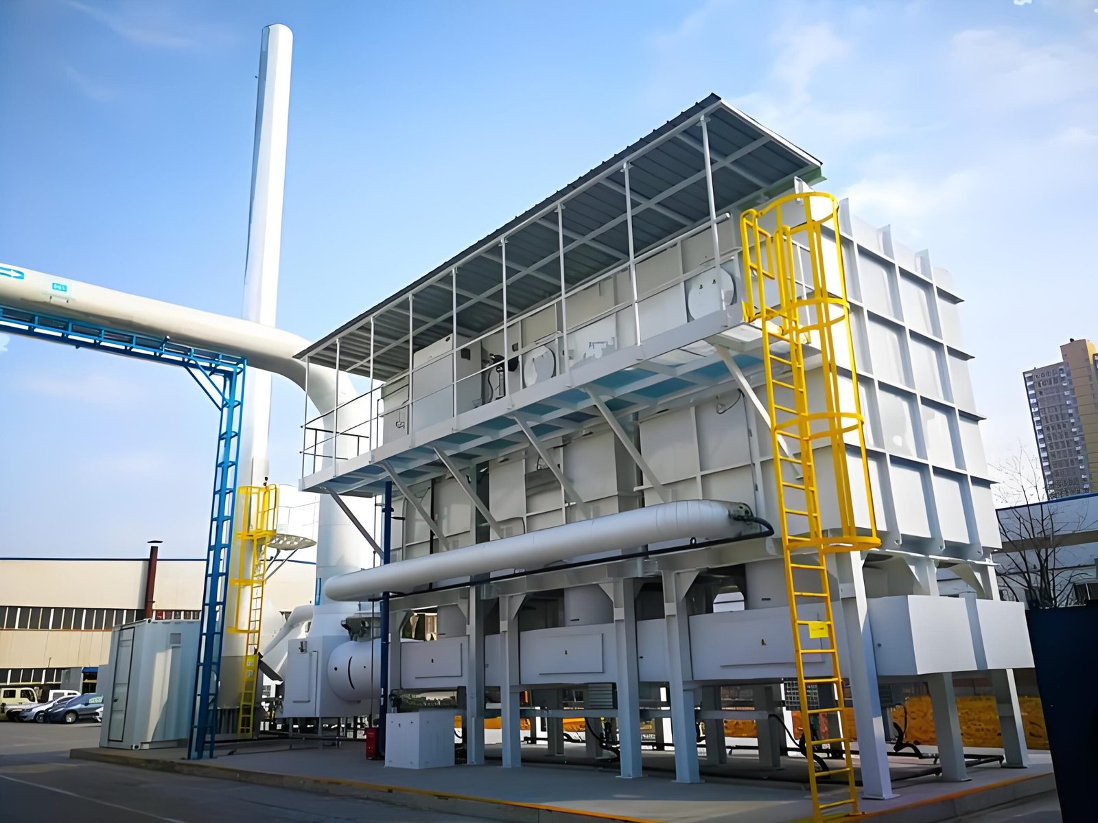
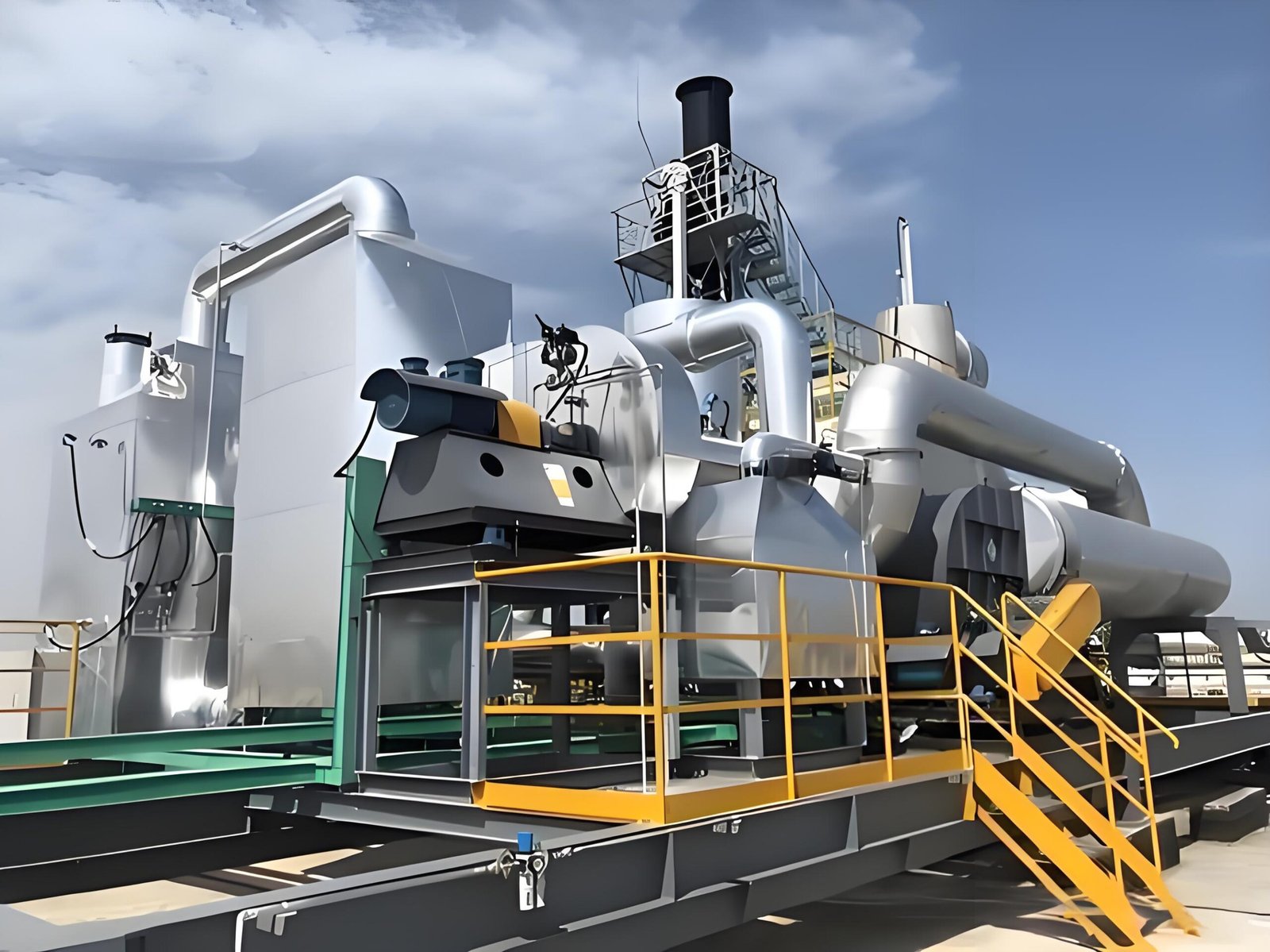
    Industrial exhaust treatment equipment showing duct connections and service access

    Where RTO may fit, and where the evaluation must continue

    A regenerative thermal oxidizer (RTO) is a commonly considered route for some continuous organic-VOC exhaust duties. It is not the automatic answer for every factory, every concentration range, or every process schedule.

    Before treating RTO as a candidate, a project team still needs the stream, airflow pattern, operating hours, material compatibility, pretreatment needs, installation space, utilities, and local requirements. Other routes can include source reduction, capture improvement, adsorption, catalytic oxidation, concentration systems, or combinations.

    SERNO’s RTO system selection guide gives a broader overview of the selection conversation. For a later quotation-stage handoff, see the VOC exhaust data checklist. Those articles come after the first source-and-capture check described here.

    A five-question factory self-check

    Use these questions to decide whether it is time to prepare for a more structured review:

    1. Which production steps use or heat materials that may release vapors?
    2. Where are those vapors captured, ventilated, or discharged today?
    3. What do the current SDS documents and process records say about the materials?
    4. When does each exhaust point run, and which lines share a fan or duct?
    5. Which local permit, inspection, emission, workplace, or environmental requirements need to be checked?

    If several answers are unclear, gather information before making an equipment commitment. A basic process/exhaust map makes a later technical discussion more specific.

    FAQ

    Does a solvent smell prove that our factory has a VOC compliance problem?

    No. A smell is not a compliance conclusion or a measurement. It can indicate that a process and exhaust path should be reviewed. The applicable requirements, compounds, exposure considerations, and testing approach depend on the site and jurisdiction.

    Is every coating or printing line a fit for an RTO?

    No. RTO can be considered for some organic-VOC duties, but the right route depends on the actual exhaust stream, operating pattern, capture arrangement, pretreatment needs, installation conditions, and local requirements.

    What should we prepare before asking for an industrial VOC treatment proposal?

    Start with the process list, material/SDS information, capture and duct sketch, operating schedule, existing controls, known changes, and the relevant local requirement. Do not invent airflow, concentration, or performance figures if they have not been measured or verified.

    Can an existing dust collector or scrubber solve VOC vapors?

    Not necessarily. Different contaminants can require different approaches. Identify the actual stream and any combined contaminants before deciding whether an existing system is sufficient or what additional treatment may be needed.

    Start with the exhaust stream, not the equipment name

    SERNO can help frame an early technical conversation around your process, materials, capture points, operating pattern, and available project information. Send the documents and site details you are permitted to share. Any final technology selection, compliance conclusion, installation scope, and operating decision must be confirmed for the installed process and applicable local requirements.
  • RTO Burner Combustion-Air Imbalance: Diagnosing Flame-Scanner Trips

    RTO Burner Combustion-Air Imbalance: Diagnosing Flame-Scanner Trips

    RTO Burner Combustion-Air Imbalance: Diagnosing Flame-Scanner Trips

    An RTO burner trip can quickly become a production problem. The visible message may be flame not proved, flame lost, or a burner-management lockout, and the first instinct is often to replace the flame scanner or adjust the burner. Either action can be premature.

    A flame-proving event is the end of a sequence, not a complete diagnosis. The burner must receive the intended start command; the required permissives must be present; the combustion-air path must be available; ignition and fuel admission must occur in the installed sequence; and the detector must receive a stable, valid flame signal. A disturbance anywhere in that chain can produce a similar alarm.

    For an engineering buyer or plant team, the useful question is: What evidence identifies the failed condition and separates it from its look-alikes? This general guide provides a structured review. It does not authorize burner adjustment, interlock bypass, fuel-train work, electrical work, chamber entry, or restart. The installed burner OEM manual, burner-management documentation, approved site procedure and qualified personnel remain controlling.

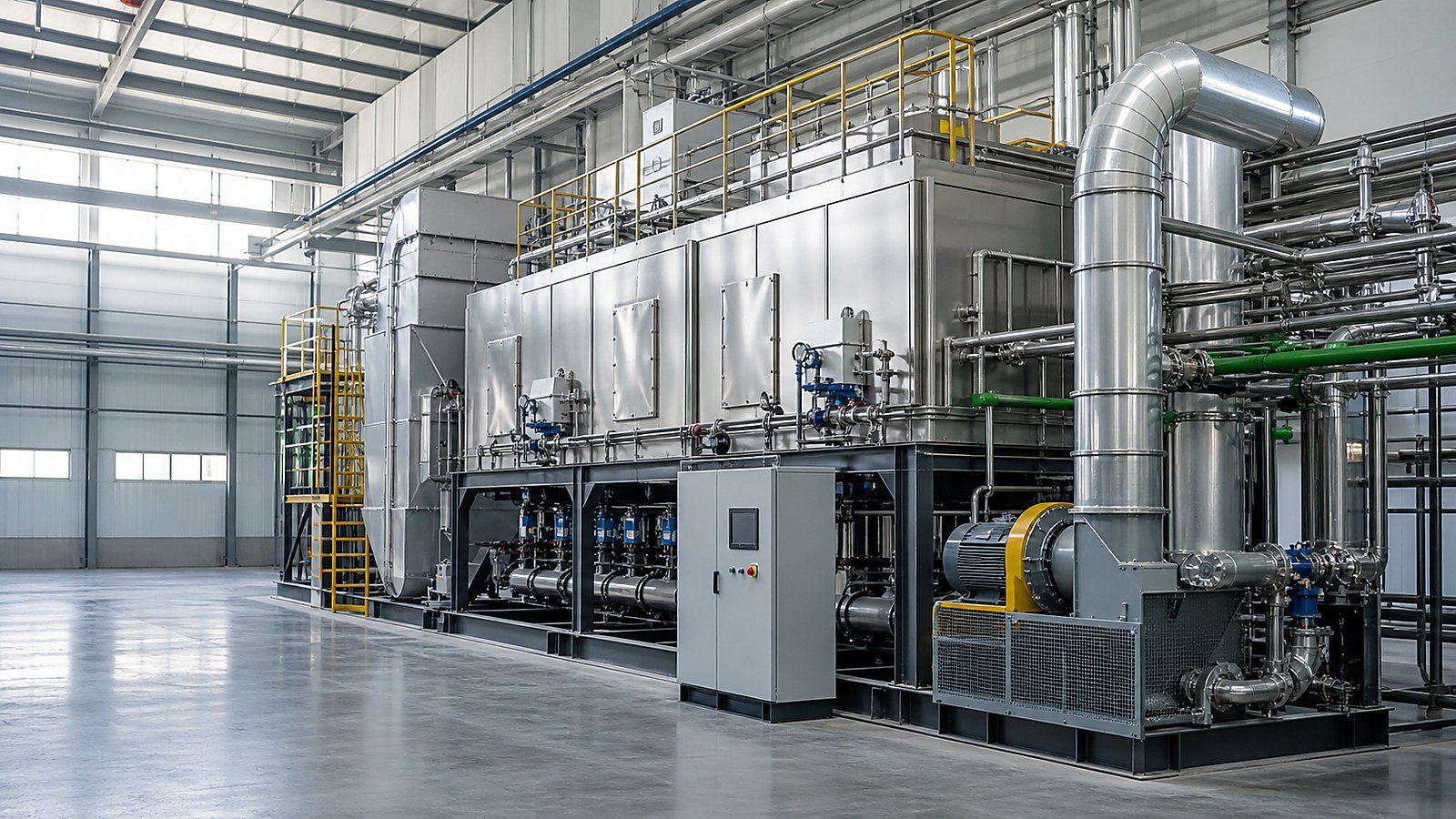
    Industrial RTO process equipment and combustion-air ductwork shown from an exterior service view

    1. Treat the alarm as a timestamped event, not a component verdict

    Start with the exact alarm text, controller event sequence and operating condition. A trip during pre-purge, at ignition, immediately after flame proof, after a period of stable operation, or during a production change may point to different evidence paths. One event code rarely tells the whole story.

    Collect data from several comparable attempts or operating cycles where this can be done safely and without forcing resets. Preserve the original record before changing parts or settings. Useful evidence includes the burner-management sequence, combustion-air fan command and feedback, relevant pressure or airflow indication, fuel-train permissive status, ignition status, flame-signal trend where available, RTO chamber temperature trend, and recent process changes.

    Event patternPlausible explanations to investigateEvidence before a repair decision
    No stable flame proof after a normal start requestCombustion-air path issue, ignition/fuel issue, detector/viewing issue, sequence or permissive issueTime-aligned sequence record; approved checks of air, fuel, ignition and detector conditions
    Flame is proved, then drops out intermittentlyAirflow disturbance, unstable combustion condition, optical contamination/vibration, wiring or power issue, process-related chamber conditionFlame-signal trend, fan status, operating state, fault timing and physical condition under approved access
    Trips occur after weather, duct, filter or fan changesChanged inlet condition, air-path restriction, fan/damper/control change, pressure reference issueCompare current and baseline air-path configuration and matched operating data
    Multiple resets are needed before it runsA transient condition is being masked, not necessarily curedReview lockout history and cause before further reset attempts; follow the installed reset policy
    Only one burner or one mode is affectedLocal burner train, detector alignment/view, wiring, local air path or logic inputCompare equivalent components and command/feedback paths using OEM-approved methods

    Do not turn this table into a fault codebook. It is a way to organize evidence and reduce unnecessary parts replacement.

    2. Confirm the combustion-air path before changing burner parts

    An RTO burner needs the air path intended by its installed design. The relevant hardware can include the combustion-air fan, inlet screen or filter, ducting, damper or actuator, pressure switches/transmitters, burner windbox, chamber connection and control wiring. A problem in any of these can affect ignition, flame stability or a permissive.

    First compare the affected event with a known-good operating period. Was the fan commanded to run? Did the command, run feedback and any installed permissive arrive in the expected order? Was a filter, inlet screen, duct, damper, VFD setting, fan belt, actuator, access door or nearby process connection changed? A signal that says a fan is commanded on is not proof of the air quantity, path integrity or pressure condition required by the burner design.

    Approved field review may need to consider:

    • fan rotation, condition, vibration and drive status;
    • inlet blockage, filter loading, screens, duct damage or unintended restrictions;
    • damper command, actual position and linkage condition;
    • pressure-sensing line condition, reference point and switch/transmitter health;
    • loose panels, access doors, leaks or changes that alter the intended air path; and
    • the relationship between burner events and RTO flow-reversal or process-exhaust changes.

    Do not infer a correct air-to-fuel setting from a generic article. The allowable air, fuel, pressure and sequence conditions are specific to the burner, fuel, chamber, controls and site approval. A qualified burner technician should use the installed documentation and approved instruments.

    3. Separate a flame-scanner problem from a combustion problem

    The flame scanner is part of the proof chain, but a weak or interrupted flame signal does not always mean the detector itself is defective. Depending on the installed technology and arrangement, the detector may be affected by its viewing path, lens/window condition, mounting, aim, heat exposure, vibration, cable integrity, electrical noise or controller input condition. A real combustion disturbance can produce the same signal loss.

    Use the event timing to guide the review. A detector fault may show a signal inconsistent with the actual burner sequence or a repeatable issue related to vibration, heat or connection movement. An air/fuel or ignition issue may track start demand, fan/damper state, fuel-train status, chamber condition or process change. These are hypotheses to test through approved OEM procedures, not conclusions to make from an alarm screen.

    For the detector path, record what can be observed safely and non-invasively: lens/window cleanliness, visible obstruction, bracket condition, cable routing and connector condition, evidence of heat damage, and whether the detector’s intended line of sight has changed. Do not clean, reposition, calibrate or replace a detector without the applicable lockout, cooldown and OEM instructions.

    4. Read the entire ignition-and-flame-proving sequence

    RTO burner systems use an installed sequence to establish safe combustion. Exact arrangements vary, but the diagnostic discipline is consistent: identify the first condition that did not occur as expected, rather than focusing only on the final lockout.

    Review pointQuestion for the installed documentation and event recordWhy it matters
    Start demand and permissivesWhich conditions must be true before the sequence starts, and which one changed?Prevents a downstream component from being blamed for an upstream inhibit
    Pre-purge / air proofDid the burner-management system receive the intended approved proof of the air path?Distinguishes an air-path or proof-input issue from a failed ignition attempt
    Ignition and fuel admissionWhat event is recorded at the point the system expects ignition and stable flame?Helps locate whether the fault occurs before or after fuel/ignition action
    Flame-signal behaviorIs the signal absent, unstable, delayed or lost after being proved?Directs the review toward detector, combustion stability or electrical evidence
    Post-flame operating stateDid the trip align with fan, damper, process, reversal or temperature changes?Reveals a disturbance that a single start record may hide

    Ask for the original controller sequence and configuration from the owner/OEM rather than relying on a generic diagram. In particular, do not copy timer values, flame thresholds, switch setpoints or reset practices from another RTO.

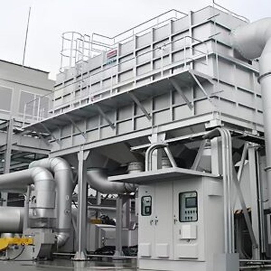
    Industrial RTO equipment with fan, ducting and stack in an outdoor installation

    5. Include process and RTO operating context

    Although the burner is local equipment, its operating context can matter. Process exhaust changes can affect RTO chamber behavior, draft and the system’s sequence of operating modes. Recent production changes, solvent substitutions, maintenance outages, fan work, duct modification, changes to bypass status, or unusual start-up/shutdown events deserve a place in the evidence package.

    This does not mean a process change caused the burner trip. It means the team should not remove potentially relevant context before an engineering review. Align the burner event with available RTO temperatures, process-exhaust flow, fan/damper state, valve/reversal state and maintenance log. If an event only occurs in one operating phase, a matched comparison is often more useful than a long list of unrelated checks.

    The U.S. EPA’s Regenerative Thermal Oxidizer fact sheet provides general background on RTO systems, retrieved 2026-07-22: https://www3.epa.gov/ttncatc1/dir1/frto.pdf. It does not provide a burner troubleshooting setting or site-specific operating instruction.

    6. Build a corrective scope from evidence

    A defensible scope identifies the observed condition, the evidence connecting it to a cause, the approved corrective action and the method for confirming the result. It should also record what remains uncertain. Examples of possible outcomes can include an instrument or wiring repair, detector-path correction, air-path repair, burner component service, a fuel-train investigation, an OEM logic/configuration review, or a process-side action. The article does not select among them.

    Before approving a scope, request:

    1. The burner make/model, installed drawings and applicable OEM documentation.
    2. Exported event/alarm history with timestamps, not only a verbal description.
    3. A comparison between an affected event and a comparable normal event.
    4. Combustion-air fan command/feedback and the approved evidence for the relevant air path.
    5. Flame-detector type, approved maintenance history and allowed inspection findings.
    6. Fuel type, fuel-train drawings and any relevant qualified-service findings.
    7. Recent change log for process, ducts, fans, dampers, controls and maintenance.
    8. The approved isolation, restart and post-repair verification plan.

    OSHA’s lockout/tagout guidance is a useful general reference for hazardous-energy control: https://www.osha.gov/lockout-tagout (retrieved 2026-07-22). Site and jurisdictional requirements remain controlling.

    7. Avoid the shortcuts that create repeat faults

    Repeated reset attempts can erase useful timing information and may contradict the installed safety procedure. Bypassing an air-proving device, flame detector, permissive or lockout is not a troubleshooting method for an operating plant. Likewise, changing fuel or air adjustments to “see if it holds” without qualified authorization can make the record less reliable and introduce risk.

    The practical aim is simpler: preserve the original evidence, establish the first failed condition, review the correct system boundary, then have qualified personnel apply the OEM-approved correction. After work, compare the same signals under comparable operating conditions and update the maintenance record. That is more useful to a technical buyer than a generic claim that a burner has been “fixed.”

    FAQ

    Does a flame-scanner trip always mean the scanner is faulty?

    No. The scanner may be affected by its viewing path, mounting, wiring, heat or controller input, but a real ignition, fuel, combustion-air or sequence issue can also prevent or interrupt flame proof. Use the timestamped sequence and OEM-approved checks to separate the possibilities.

    Can a combustion-air fan issue cause an RTO burner lockout?

    It can contribute if the installed burner-management system does not receive the intended air-path condition or if combustion stability is affected. The precise proof method and corrective action depend on the installed fan, controls, burner and approved documentation.

    Is it safe to reset an RTO burner repeatedly after a flame-failure alarm?

    Follow the installed OEM and site procedure. Repeated resets can obscure evidence and may not be permitted. A qualified review should determine why the sequence did not complete before restart.

    What data should we send for a preliminary burner troubleshooting discussion?

    Share the burner/RTO drawings where permitted, alarm sequence and timestamps, normal-versus-fault event records, fan/damper status, available temperature/process trends, recent changes, maintenance history and the applicable safety requirements. Do not share credentials or bypass safety controls to collect data.

    Related SERNO engineering resources

    Need to structure an RTO burner troubleshooting review?

    Send SERNO the available event history, installed drawings, process-exhaust range, combustion-air/fan information and description of recent changes. We can help structure the technical questions for an engineering discussion. Final service and operating decisions must be confirmed against the installed equipment, OEM documentation and site requirements.

  • RTO Ceramic Media Fouling: How to Diagnose Rising Pressure Drop

    RTO Ceramic Media Fouling: How to Diagnose Rising Pressure Drop

    RTO Ceramic Media Fouling: How to Diagnose Rising Pressure Drop

    When an RTO differential-pressure trend rises, the first conclusion is often simple: “the ceramic media is plugged.” Ceramic media can accumulate dust, sticky condensables, salts, corrosion products, or other deposits. But a changing pressure reading can also be caused by a new airflow condition, a restricted upstream device, a damper that is not in its intended position, a duct change, an impulse-line problem, or a transmitter with the wrong reference point.

    For a plant team or technical buyer, the useful question is not “How soon can we replace the media?” It is: What evidence identifies the restriction, its likely mechanism, and the safest corrective scope? Replacing media without that evidence can leave the original contaminant source in place. Increasing fan speed without it can hide a developing restriction while adding energy use and mechanical load.

    This is a general engineering guide. It does not prescribe a universal acceptable pressure drop, cleaning method, replacement interval, or isolation procedure. The installed RTO’s OEM documentation, site permit, approved safety review, and operating data remain controlling.

    Regenerative thermal oxidizer equipment and ductwork in an outdoor industrial installation

    1. Why ceramic media matters to pressure drop

    RTO ceramic media stores heat from treated gas and transfers that heat to incoming process exhaust during the next flow-reversal step. The media bed must provide a large heat-transfer surface while still allowing the intended gas flow to pass through. Its geometry, bed depth, support arrangement, gas distribution, contamination exposure, and switching configuration all affect resistance to flow.

    Deposits can reduce open area or change the effective flow path. Fine dust may lodge in channels; sticky material can capture more particulate; condensed high-boiling compounds may bind particles together; corrosive or abrasive constituents can damage surfaces or supports. Those mechanisms are project-specific. A clean solvent exhaust does not behave like a stream carrying powder, paint mist, resin aerosol, silicon-containing compounds, acid gases, or intermittent wash-up vapour.

    But ceramic media is only one part of the gas path. A differential-pressure signal may span a whole RTO section, not only a bed. Before diagnosing the media, confirm precisely where pressure is measured and what conditions existed when the reading changed.

    2. First confirm that the trend is comparable

    One pressure value has little meaning without its operating context. Compare readings taken at the same instrument points, fan mode, airflow range, valve state, production condition, and—where relevant—flow-reversal phase. A higher process airflow normally creates a higher pressure loss even when equipment condition is unchanged.

    Build a time-aligned evidence set before planning invasive work:

    EvidenceCompareWhy it matters
    Differential pressureSame taps, range, zero check, and reversal phaseSeparates a real trend from a reference or transmitter issue
    Airflow and fan dataActual flow, speed, damper position, current/power, static pressureShows whether a changed operating point explains the reading
    Bed/chamber temperaturesComparable points across several cyclesMay reveal uneven flow or a bed behaving differently from its counterpart
    Process recordProduct, solvent, batch, cleaning, dust/mist source, uptimeIdentifies a new contaminant or loading condition
    Valve and bypass statusCommand, feedback, travel alarms, manual overridesChecks whether gas is following the intended path
    Maintenance historyFilter changes, duct work, pretreatment issues, prior depositsLinks the trend to a plausible mechanism

    Trend at a resolution that can see complete operating cycles. Daily averages may obscure a cycle-linked restriction or a signal that shifts only when a valve state changes. Conversely, do not diagnose an RTO from one abnormal shift; capture comparable operation and record unusual process events.

    3. Separate ceramic fouling from other restrictions

    An RTO pressure-drop increase can originate upstream, inside the unit, or downstream. The following table is not a fault codebook; it helps direct the next evidence check.

    Observed patternPlausible explanationsEvidence before approving work
    DP rises with airflow and returns at lower flowNormal system curve, changed fan setpoint, production expansionCompare matched airflow conditions and fan operating point
    DP is high across all operating modesRestricted filter, duct, silencer, stack path, transmitter/reference issueWalk down the full approved pressure path; inspect instrument impulse lines and recent duct changes
    One bed or reversal state differs repeatedlyLocal media fouling, distribution issue, valve position/travel issue, local sensor issueAlign DP, valve command/feedback, temperature, and reversal timing
    DP rose after a process/material changeNew dust, mist, condensable or corrosive carryoverReview material list, collection points, pretreatment performance, and sampling/inspection evidence
    Pressure signal is noisy or implausiblePlugged/leaking impulse lines, condensate, loose fitting, damaged transmitterVerify instrument condition and zero/reference using the approved site method

    This sequencing protects both the plant and the procurement decision. If a clogged prefilter or altered duct branch is the root cause, media replacement will not correct it. If the media is contaminated, the upstream source and any missing pretreatment should be addressed with the media scope.

    4. Check the inlet and pretreatment boundary

    RTO media is not a general-purpose dust collector or mist eliminator. The project’s inlet boundary should be reviewed whenever a deposit is suspected. Ask what reaches the RTO in normal operation, at start-up/shutdown, during cleaning, and after any process change.

    Items to review include:

    • dust, powder, fibre, pigment, spray overspray, or abrasive particulate;
    • oil mist, plasticizer, resin, adhesive, or other sticky aerosol;
    • high-boiling or condensable VOC components and cold duct sections that can create carryover;
    • acid-gas, sulfur, halogen, silicon, or other constituents that may affect material selection or deposit behaviour;
    • filters, cyclones, mist separators, duct drains, hoods, and collection velocities; and
    • new production lines, changed recipes, solvent substitutions, or temporary bypasses.

    Do not infer chemistry from appearance alone. A dark layer, white deposit, or glazed surface can have several causes. If the approved site procedure allows sampling, document the location, operating condition, chain of custody, and analysis method before selecting cleaning chemicals or replacement media. Any sample or inspection activity must follow the site’s approved cooldown, isolation, access, and exposure controls.

    RTO process equipment showing duct routing and access platforms in an industrial setting

    5. Inspect the gas path and media bed safely

    Physical inspection should be planned only after the evidence points to an internal restriction and the owner approves the work. The exact requirements for lockout/tagout, cooldown, confined-space entry, elevated work, gas testing, respiratory protection, and waste handling are site-specific. This article cannot authorize access to an RTO chamber or duct.

    An approved inspection scope may need to check:

    • media surface condition, channel openness, evidence of bridging, erosion, collapse, or foreign material;
    • bed depth, levelness, support grids, retaining hardware, and distribution plates;
    • nearby transitions, expansion joints, ducts, dampers, and purge paths for restrictions or displaced insulation;
    • valve travel and actual gas-path configuration during the affected operating state;
    • access-door seals and pressure taps; and
    • representative documentation: location-marked photos, dimensions, deposit description, and an operating-data snapshot.

    Avoid a “clean everything” scope until the deposit mechanism is understood. Aggressive mechanical cleaning can damage fragile media or supports; an unsuitable wash can create secondary contamination or corrosion. The equipment supplier’s media specification and the site’s waste/disposal controls should be reviewed before a method is chosen.

    6. Use data after the intervention—not just before it

    Whether the action is instrument repair, duct correction, pretreatment improvement, controlled cleaning, partial media repair, or media replacement, repeat the same measurement method under comparable operating conditions. Preserve the pre-work evidence and record the changed condition.

    A useful close-out record includes:

    1. The observed symptom and its time-aligned data.
    2. The confirmed restriction or other root cause, including evidence and uncertainties.
    3. The scope performed and materials used.
    4. Any upstream process or pretreatment correction.
    5. Post-work pressure, airflow, temperature, valve-state, and analyzer checks taken under comparable conditions.
    6. Updated drawings, maintenance history, inspection triggers, and spare-parts information.

    This record is more valuable than a generic statement that the RTO is “clean.” It creates a baseline for the next shift in trend and helps an engineering buyer compare a proposed repair scope with the actual failure mode.

    7. Do not use fan changes as a substitute for diagnosis

    Higher fan speed can restore flow temporarily, but it may also raise energy use, noise, duct velocity, and mechanical load. It does not remove deposits or correct a restricted path. Likewise, a stable fan current does not prove the media is clean; fan response depends on the whole system curve and control arrangement.

    The earlier SERNO guide on RTO pressure drop and fan sizing addresses design selection and component budgeting. This diagnostic guide addresses a change from a proven operating baseline. In either case, compare suppliers and corrective actions on the same stated airflow, pressure basis, process condition, and system boundary.

    8. A practical buyer checklist before approving a media scope

    Before placing an order for cleaning, media, a fan modification, or an outage service, ask for the following in writing:

    1. Which pressure points and airflow conditions established the problem?
    2. Is the reading compared with a valid historical baseline at equivalent operating conditions?
    3. Which upstream/downstream restrictions and instrument faults were excluded?
    4. What evidence connects the observed deposit or restriction to the proposed work?
    5. What inlet contaminant, process event, or pretreatment gap is being corrected to prevent recurrence?
    6. What media specification, support-system checks, handling method, and waste controls apply?
    7. What post-work measurements will confirm the result, and under what process conditions?
    8. Which assumptions remain unverified and require owner/OEM review?

    General RTO context is available in the U.S. EPA’s Regenerative Thermal Oxidizer fact sheet, retrieved 2026-07-21. It is background information, not a performance guarantee or maintenance instruction for a specific installation.

    FAQ

    Does a higher RTO pressure drop always mean ceramic media is plugged?

    No. It may be caused by higher airflow, a changed fan/damper state, a restriction elsewhere in the gas path, a valve-path issue, or an instrument/reference problem. Compare matched operating data and inspect the approved system boundary before concluding that the media is fouled.

    Can ceramic media be cleaned instead of replaced?

    Possibly, but the decision depends on the media type, deposit chemistry, structural condition, support system, equipment manufacturer guidance, and approved safety/waste controls. Cleaning should not be selected before identifying the deposit mechanism and confirming that the media remains suitable for service.

    What process conditions commonly create media-fouling risk?

    Dust, powder, mist, sticky aerosols, condensable material, corrosive constituents, and inadequate collection or pretreatment can all contribute. The relevant risk depends on the actual exhaust composition, temperature profile, and operating events—not only the industry name.

    Should we increase fan speed when the pressure trend rises?

    Only after the owner’s engineering review. Fan changes may mask a restriction and alter energy use or equipment loading. First establish whether airflow changed, where the restriction is, and whether the operating point remains within the installed equipment’s approved envelope.

    What data should be sent for a preliminary RTO diagnostic discussion?

    Provide historical and current differential pressure, airflow, fan speed/current, temperature trends, valve/bypass status, process and material changes, exhaust composition, pretreatment details, photos from any approved inspection, and the installed P&ID/O&M information where shareable.

    Related SERNO engineering resources

    Need to review a changed RTO pressure-drop trend?

    Send SERNO the matched operating data, exhaust composition, pretreatment details, equipment drawings, and a description of any recent process change. We can help structure the technical questions for an RTO diagnostic or corrective-scope discussion. Final recommendations must be confirmed against the installed system and site requirements.

  • RTO Valve Leakage: Diagnosing Outlet VOC Spikes and Heat Loss

    RTO Valve Leakage: Diagnosing Outlet VOC Spikes and Heat Loss

    RTO Valve Leakage: Diagnosing Outlet VOC Spikes and Heat Loss

    An outlet VOC rise, an unexpected change in auxiliary-fuel demand, or a temperature pattern that no longer repeats cleanly can trigger a familiar conclusion: “the RTO valves must be leaking.” Sometimes that is correct. Often, it is only the beginning of the investigation.

    RTO flow-reversal valves work in a demanding environment. They repeatedly direct hot process gas through ceramic beds, isolate paths during switching, and must do so while the process, duct network and controls are changing around them. A worn seal, a distorted seat, incomplete travel or mist/dust deposits can affect performance. But similar symptoms can also come from inlet concentration changes, a bypass path, purge configuration, a fan/duct problem, a sampling-system issue, or a control sequence that no longer matches the installed hardware.

    For plant teams and technical buyers, the useful question is not “Can you replace our valves?” It is: What evidence shows where the gas is travelling, when the symptom occurs, and whether a valve repair is actually the right scope? This guide provides a general engineering diagnostic framework. It does not set a universal leakage limit or replace the installed RTO manual, approved isolation procedure, permit conditions, or site safety review.

    Industrial regenerative thermal oxidizer and connected ductwork

    1. Why valve sealing matters in a regenerative system

    An RTO recovers heat by alternating gas flow through ceramic media. In a typical multi-bed arrangement, one bed is heated by treated gas while another preheats incoming process gas; a short purge or transition step may be used as the system reverses. The transfer-valve system is therefore part of the gas-path design, not a peripheral accessory.

    If a valve does not seal or does not reach its commanded position, gas can take a path the control philosophy did not intend. Depending on the configuration, the observed effect may be residual untreated gas mixing with the treated stream, temperature imbalance between beds, additional cold-air ingress, a shifted purge volume, or lower apparent thermal recovery. The effect is not identical for every RTO: bed count, valve type, purge arrangement, VOC stream, fan location and operating mode all matter.

    That is why a single outlet analyzer value is not enough to diagnose valve leakage. It reports a result at one point in the system; it does not, by itself, identify the path that created that result.

    2. Recognize the symptoms—but treat them as clues, not proof

    Suspected valve leakage often begins with a trend rather than a visible failure. The most valuable first step is to preserve that trend and compare it with the operating sequence.

    Possible clues include:

    • outlet VOC peaks that recur at or shortly after flow reversal;
    • a growing difference between the temperature profile of nominally comparable beds;
    • a change in fuel demand after process conditions are normalized for review;
    • valve-position alarms, slow switching, repeated retries or feedback mismatch;
    • a change in stack oxygen, pressure or flow trend that coincides with a switching event;
    • deposits, corrosion, damaged insulation or abnormal noise near a valve housing; and
    • a poor correlation between a portable check and the permanently installed analyzer.

    Each clue has alternatives. A peak after reversal may be a purge-volume or analyzer-response issue. More fuel may be caused by lower inlet VOC concentration, excess air, air ingress, changed airflow or a damaged heat-exchange path. A position indicator can say “closed” even when a seal face is not fully seated. The diagnostic aim is to make those alternatives visible, not to choose one based on the first alarm.

    3. Start with a controlled evidence pack

    Before isolating equipment or ordering components, collect a time-aligned record over representative operating modes. The exact tags available will differ, but the following evidence pack makes a supplier or maintenance team far more effective.

    EvidenceWhat to compareWhat it can help distinguish
    Outlet VOC trendAnalyzer timestamp versus every valve reversal and purge stepCycle-linked peaks versus process-driven variation
    Inlet VOC, airflow and temperatureNormal, low-load, high-load, batch and cleaning conditionsChanged inlet heat value or gas volume versus equipment degradation
    Bed and chamber temperaturesSame point in each cycle, not only daily averagesRepeatable bed imbalance or abnormal thermal carryover
    Valve command and feedbackCommand time, end-position feedback, travel time, retries and fault bitsSlow, incomplete or inconsistent actuation
    Fan, duct and stack pressureBefore/after reversal and against historical baselineAir ingress, flow disturbance or an unintended open path
    Analyzer recordsCalibration, sample flow, filters, heated-line condition, response delayMeasurement fault before mechanical intervention
    Maintenance historySeal material, actuator work, deposits, recent duct/process changesLikely wear mechanism and changes in the original design basis

    Trend at a resolution that can see a whole reversal cycle. A daily average can hide a short excursion completely. At the same time, avoid declaring a fault from one cycle: capture comparable runs and note abnormal process events such as solvent changeover, wash-up, line stoppage or manual override.

    4. Check the measurement chain before opening the valve system

    An analyzer can be correct and still be telling the wrong diagnostic story if its sample is delayed, diluted, contaminated or not representative. Review where the sample probe sits, whether the line is heated where required, sample conditioning, filter condition, sample-flow alarms, calibration records, zero/span behavior and the known transport delay from probe to reading.

    Then align the analyzer timebase with the PLC or historian. If a suspected event is only a few seconds long but the sample system has a longer or variable delay, the apparent peak may not line up with the actual valve event. A comparison with an approved portable method may be useful, but only when the method, location and safety controls are defined by the site. Do not open hot ducts or introduce an ad-hoc test point merely to obtain a quick reading.

    This review also prevents a common procurement error: replacing seals because the permanent analyzer drifted or its sample path became restricted. A verified measurement chain turns a repair decision from a guess into an engineering decision.

    5. Inspect the valve, actuator and sealing environment as one system

    Once the operating evidence points toward the transfer-valve system, planned inspection should examine more than the seal itself. Exact lockout, cooldown, confined-space and hot-work requirements are site-specific and must be approved before access.

    For the installed valve design, the inspection plan commonly needs to consider:

    • seat, seal and contact surface condition: tearing, hardening, compression set, erosion, warping, deposits or corrosion;
    • disc/poppet, damper blade or lifting mechanism alignment and evidence of rubbing;
    • actuator torque/force, air supply or hydraulic/electrical condition, linkage wear and mechanical stops;
    • actual end travel versus feedback-switch or encoder indication;
    • housing distortion, loose fasteners, insulation damage and thermal expansion allowance;
    • particulate, condensable mist, sticky polymer, acid-gas or abrasive-dust exposure that can damage sealing surfaces; and
    • the condition of adjacent dampers, bypass paths, purge ducting and expansion joints.

    Do not treat a closed-limit switch as a seal-verification test. It proves a selected mechanical or electrical point has been reached; it may not prove full contact along a hot, loaded sealing surface. The equipment manufacturer’s inspection method and acceptance criteria should govern the final judgment.

    Industrial fabrication environment for equipment inspection and maintenance

    6. Use the switching sequence to separate likely causes

    The timing of the symptom is a powerful diagnostic tool. Review the PLC sequence, operator actions and physical feedback together. The table below is not a fault codebook; it is a way to decide which evidence deserves the next inspection step.

    Observed patternPlausible explanations to testPractical next check
    Outlet peak repeats immediately after each reversalValve-seat leakage; purge volume/timing; analyzer transport delay; outlet-side mixingAlign raw analyzer, PLC state and purge tags over several cycles; verify sample-path delay before changing hardware
    One bed diverges from comparable beds over several cyclesValve sealing/travel issue; blocked or contaminated media path; uneven inlet distribution; thermocouple issueCompare temperature trend, position feedback and pressure pattern; inspect instruments before opening media or valves
    Fuel demand rises with lower inlet VOC concentration or higher airflowChanged process heat contribution; flow/air ingress; thermal-recovery lossNormalize the review for representative process load and verify airflow/pressure data
    Feedback shows a completed stroke but travel time is variableActuator supply issue; linkage wear; binding; loose target/camReview stroke trend and physical end travel using the approved maintenance method
    Outlet reading is unstable without a consistent cycle relationshipInlet variability; analyzer/sample fault; downstream leak/mixing; process upsetAudit sampling and process data first; do not presume a valve cause

    If a leak path is confirmed, capture the condition before repair and repeat the same approved checks after repair. That before/after record is more valuable than a verbal statement that the equipment “looks better.” It helps confirm whether the repair addressed the observed failure mode and gives the owner a baseline for future maintenance.

    7. Protect thermal recovery without making unsupported promises

    Valve condition can influence thermal recovery, but the relationship is system-specific. Fuel use also changes with inlet VOC concentration, moisture, airflow, combustion temperature, ambient conditions, excess air, insulation condition, bypass operation and production schedule. Comparing monthly fuel totals alone can create a misleading conclusion.

    For a meaningful review, select equivalent production periods or normalize the operating data as far as the available tags allow. Compare inlet flow and temperature, VOC loading where reliable, bed temperatures, combustion-chamber setpoint, fuel flow, stack conditions, valve state and the duration of each operating mode. Document any changed solvent, recipe, duct branch, fan setting or process line.

    General RTO design information is available from the US EPA’s Regenerative Thermal Oxidizer fact sheet (source checked 2026-07-20). It is useful background, not a performance guarantee for a particular unit. The operating data and the installed design documents must determine what recovery change is credible at your plant.

    8. Turn the diagnosis into a maintainable repair scope

    The best repair scope includes the root cause and the evidence needed to detect recurrence. If deposits caused the seal problem, replacing the seal alone may not be enough; the upstream mist, dust, condensable or temperature issue must be reviewed. If the actuator is underpowered or the linkage is binding at temperature, a new seal may fail quickly. If the root cause was a configuration change, update the drawings and control narrative.

    Ask a repair supplier or internal team to define the following in writing:

    1. The observed failure mode and the evidence that supports it.
    2. Parts/material specification compatible with temperature, chemistry and mechanical duty.
    3. Required inspection or alignment measurements before reassembly.
    4. Actuator, feedback, interlock and sequence checks after reassembly.
    5. The approved method for confirming the gas-path performance after the work.
    6. Any upstream mitigation, cleaning interval, spares or inspection frequency proposed—and the condition that triggers it.
    7. Updated drawings, maintenance records, setpoint-change control and operator handover.

    Maintenance intervals should be condition-based wherever possible. A calendar interval can be a useful starting point, but it cannot substitute for trends, inspections and process-change review. The same principle applies to any “acceptable leakage” number: use the OEM and project-specific criteria rather than borrowing a value from a different valve design or service.

    FAQ

    Can high outlet VOC prove that an RTO valve is leaking?

    No. It is a symptom that needs to be compared with the valve cycle, inlet conditions, purge sequence, pressures and analyzer performance. A controlled evidence pack is needed before calling it a valve fault.

    What is the first check when an outlet peak appears after reversal?

    Confirm the analyzer/sample-path response and align its timestamps with the PLC state and purge timing across several comparable cycles. This avoids confusing an instrument delay or purge effect with a mechanical leak.

    Does a closed-position limit switch prove that the valve seals?

    Not necessarily. It proves the configured feedback point has been reached. Seal contact under operating conditions may require a separate approved inspection or test method for the installed valve.

    Will replacing a valve seal reduce fuel consumption?

    It may help if a confirmed gas-path fault is affecting thermal recovery, but fuel use has multiple causes. Compare normalized operating data before and after an approved repair; do not promise a savings figure without plant-specific evidence.

    What information should be sent for a valve-maintenance quotation?

    Provide the RTO model/configuration, valve drawings/photos where permitted, process gas and temperature range, operating trends, alarm history, valve command/feedback data, maintenance records, contaminants/deposits, safety requirements and the desired scope of testing/documentation.

    Discuss the evidence before approving the repair

    SERNO can help review the information needed for an RTO valve-maintenance scope: configuration, process conditions, cycle trends, inspection findings and the documentation required for your project. Start with the RTO product overview, compare operating considerations in the RTO maintenance checklist, review RTO pressure drop and fan sizing, and send the available data through the project inquiry form. Final diagnosis, safety controls and acceptance criteria must be confirmed for the installed system and site.

  • RTO Safety Interlocks and LEL Management: An Engineering Guide

    RTO Safety Interlocks and LEL Management: An Engineering Guide

    RTO Safety Interlocks and LEL Management: An Engineering Guide

    RTO safety is not a single sensor, a single alarm, or a percentage copied from a previous project. It is an engineered chain: understand the exhaust stream, prevent an unsafe combustible mixture from reaching the oxidizer, prove that the equipment is ready to operate, and move the plant to a defined safe state when a critical condition is lost.

    For EHS teams and technical buyers, the practical question is not simply “Does the RTO have LEL monitoring?” It is: Which conditions are measured, what assumptions sit behind each setpoint, what action follows a fault, and how is that action validated before start-up? This guide explains the questions that belong in an RTO specification and quotation review. It is general engineering information, not a replacement for a HAZOP, process safety review, or the requirements adopted by the authority having jurisdiction.

    Industrial regenerative thermal oxidizer for VOC treatment

    1. Why combustible-mixture management comes before equipment sizing

    An RTO oxidizes VOCs at elevated temperature. That makes it effective for suitable industrial exhaust, but it also means the inlet stream must be characterized for flammability, concentration variation, oxygen content, temperature, pressure, mist, dust, and possible contaminants. A nominal average concentration is not enough. Batch charging, solvent changeover, line cleaning, fan stops, and duct interactions can create short-duration peaks that are not visible in a monthly production average.

    LEL—the lower explosive limit—is a property of a combustible material in a stated oxidant and temperature condition. Real exhaust can contain several solvents, humidity, inert gases, and changing oxygen levels. The mixture behaviour can differ from a single-component data sheet. A design team should therefore establish the relevant worst credible operating cases and the analytical method, sampling location, response time, and calibration plan used to monitor them.

    The correct operating limit is project-specific. It must be set by the applicable code, the selected safety philosophy, and competent process-safety review. A supplier brochure or generic post cannot establish a safe setpoint for a particular plant.

    2. The safety layers an RTO buyer should expect

    Good RTO safety design uses layers so that no single ordinary control failure becomes a hazardous event. The exact architecture varies by jurisdiction and process, but a quotation should distinguish the following functions.

    Safety layerEngineering purposeBuyer review question
    Process designKeeps normal exhaust composition and flow within the approved envelopeWhat normal, peak, startup and upset cases were used?
    DetectionIdentifies relevant concentration, flow, temperature, pressure, valve or flame conditionsWhich instruments are safety-critical, and where are they located?
    PermissivesPrevents start-up unless required conditions are provenWhich conditions must be true before fan, burner and valves can run?
    Trips/interlocksTakes a defined action when a hazardous condition is detectedDoes each trip specify alarm, shutdown action, reset method and cause?
    Mechanical/process safeguardsProvides robust backup where controls alone are insufficientAre isolation, relief, ventilation, dilution, flame protection or bypass arrangements included where the review requires them?
    Procedures and proof testingMaintains the design over timeWho owns calibration, functional testing, change management and records?

    An HMI screen is not proof of an independent safety function. Ask the engineering team to identify the instruments, logic solver or safety relay where used, final elements, diagnostic coverage, test intervals, and failure response. The appropriate independence and performance requirements should come from the project risk assessment, not a marketing claim.

    3. What an LEL monitoring design must define

    “LEL monitor included” is incomplete wording. A useful specification identifies the analyser technology and its limitations, the sample conditioning arrangement, the location of the sample point, expected transport delay, alarm/trip philosophy, calibration gas and frequency, and how failed or out-of-range readings are handled.

    Sampling points must represent the stream that can enter the oxidizer. A point too far upstream can miss downstream solvent addition, leakage, or dilution; one too close to a turbulent branch may give unstable readings. Heated lines, filtration, condensate control, and a sample-flow failure alarm may be required depending on the stream. Some gas mixtures, mists, or compounds have limitations with a particular sensor technology. The analyser supplier and process-safety team should review cross-sensitivity and poisoning risks before final selection.

    The logic should define at least four states: healthy reading within the approved envelope; alarm; trip; and analyser/system fault. Treating a failed analyser as a healthy zero reading is not an acceptable assumption. The specified safe action may be to stop VOC introduction, isolate a source, maintain or stop extraction according to the process design, purge, or shut down the RTO in a controlled sequence. The action must be designed with the production process so that it does not create a separate exposure or emission problem.

    4. Start-up permissives and purge are part of the safety function

    Before ignition or introduction of VOC-bearing gas, an RTO normally needs a defined sequence that confirms the equipment and gas path are ready. The final sequence must follow the approved design and applicable standard, but a buyer can ask whether it accounts for the following:

    • correct fan status and proven airflow/draft;
    • required damper and isolation-valve positions;
    • a completed, measured purge of the relevant volume before burner ignition;
    • burner management system checks such as flame supervision and fuel-valve proving where applicable;
    • acceptable temperature/pressure conditions and no active emergency stop;
    • healthy safety instruments and communications required by the approved logic;
    • confirmation that the process stream is within its approved composition envelope before admission.

    Purge volume and duration cannot be chosen from a rule of thumb without considering the actual connected volume, flow path, fan performance, damper positions and possible dead legs. The sequence should be documented so commissioning personnel can verify it, and so maintenance changes do not silently invalidate the calculation.

    5. Interlocks need clear cause-and-effect documentation

    For every major trip, request a cause-and-effect matrix. It should show the initiating signal, alarm level, automatic action, annunciation, shutdown sequence, reset conditions, manual action required, and any signal that must remain available after the trip.

    Typical causes to address in the project review include high combustible-gas indication, analyser fault, loss of extraction airflow, burner/flame fault, abnormal chamber temperature, high differential pressure where relevant to the configuration, critical valve-position discrepancy, emergency stop, and loss of required utility. The matrix should explain what happens to the VOC source, the RTO fan, fuel, inlet/outlet dampers, purge cycle, valve system and bypass—if a bypass exists. “System shuts down” is too vague for a purchase specification.

    Avoid designing one trip in isolation. For example, stopping an exhaust fan can change the pressure balance of a process area; opening or closing a damper can affect dilution and the path to stack. The safe state needs to be evaluated across the RTO, duct network and production process.

    6. Commissioning is where assumptions become operating evidence

    Factory and site commissioning should verify both normal operation and safe response. A written test plan should list the instrument loop checks, calibration certificates, programmed setpoints under change control, interlock functional tests, burner-management tests, valve/damper travel checks, airflow verification, purge verification, alarm annunciation, emergency-stop response, and restoration procedure.

    Testing should use approved methods that do not introduce combustible gas or create an unsafe condition. Simulation may be appropriate for some inputs; other checks need field confirmation of actual flow or device movement. Each test needs an acceptance criterion and a signed record. If any cause-and-effect action is changed after commissioning, repeat the affected proof test and update drawings, logic narratives and operator procedures.

    Technicians checking industrial control equipment during RTO commissioning

    7. Procurement checklist: questions to send with an RFQ

    Send enough process information for the supplier and safety team to engineer the system rather than guess. The following checklist helps start the conversation:

    1. Normal, maximum, minimum and upset exhaust airflow, temperature and pressure.
    2. VOC species, concentration range, batch/cleaning peaks, oxygen content, humidity, dust, mist and corrosive components.
    3. Lower-explosive-limit data and mixture assessment provided or validated by qualified parties.
    4. Process operating modes, simultaneous sources, changeover sequence and future expansion plans.
    5. Applicable local codes, permit requirements, hazardous-area classification and owner safety standards.
    6. Required shutdown philosophy for the process and treatment system.
    7. Requested instrument list, cause-and-effect matrix, P&ID, electrical classification, control narrative and commissioning test records.
    8. Ownership of calibration, proof testing, spare sensors/parts and management of change after handover.

    The goal is not to turn a quotation into a safety case. It is to make the quotation transparent enough that the owner can compare safety scope, engineering assumptions and lifecycle responsibilities fairly.

    8. Common mistakes to prevent during operation

    The most persistent safety weaknesses are often introduced after the equipment is delivered: a new solvent is used without review, an analyser calibration is deferred, a nuisance trip is bypassed, a duct branch is added, or a software setting is changed without updating the cause-and-effect matrix. These are management-of-change issues, not simply maintenance issues.

    Keep an approved operating envelope and train operators on what happens outside it. Investigate repeated alarms; do not normalise them. Preserve calibration and functional-test records. When a process change may affect VOC concentration, oxygen, airflow, temperature, contaminants or connected volume, bring the RTO engineer and safety owner into the review before the new condition is operated.

    FAQ

    Is one fixed percentage of LEL safe for every RTO?

    No. A setpoint must be determined for the actual mixture, process, equipment configuration, safety strategy, and the code adopted for the project. This article intentionally does not prescribe one universal number.

    Does an LEL analyser alone make an RTO safe?

    No. It is one element in a system that also needs valid process data, appropriate sample design, permissives, shutdown logic, purge/ignition controls, mechanical safeguards as required, procedures and proof testing.

    What should happen if an LEL analyser fails?

    The approved safety philosophy must define this. The failure needs to be detected, alarmed and brought to a defined response; it should not be treated as a healthy measurement. The response must be coordinated with the process and emission-control design.

    Can an RTO safely accept any solvent stream if it has dilution air?

    No. Dilution is a design measure that requires validated flow, mixing, control and failure analysis. Solvent composition, peak concentration, oxygen content, temperature, contaminants and operating variability still require review.

    Which documents should be requested before acceptance?

    At minimum, request the P&ID, instrument list, control/sequence narrative, cause-and-effect matrix, electrical/hazardous-area information where applicable, approved operating envelope, commissioning test record, calibration/proof-test plan, and operating/maintenance manuals.

    Related SERNO engineering resources

    Need an RTO safety-scope review?

    Send SERNO the exhaust-flow range, VOC composition and concentration range, process modes, existing safety requirements and local project location. We can help define the engineering information needed for an RTO/Rotor RTO proposal. Final safety design and code compliance must be verified for the specific project by competent parties and the applicable authority.

  • RTO Residence Time and Combustion Chamber Sizing: An Engineering Guide

    RTO Residence Time and Combustion Chamber Sizing: An Engineering Guide

    SERNO Knowledge Center · RTO Engineering

    RTO Residence Time and Combustion Chamber Sizing: An Engineering Guide

    Residence time is one of the three fundamental conditions for thermal oxidation: temperature, time and turbulence. Yet it is often misunderstood during RTO quotation comparison. A chamber that looks large externally does not automatically provide adequate residence time, and a calculation based on ambient airflow can significantly underestimate the required hot-zone volume.

    RTO combustion chamber cutaway illustration showing internal gas path

    What residence time means in an RTO

    In an RTO, residence time is the average period during which the VOC-bearing gas remains within the oxidation zone at or above the specified oxidation temperature. During this period, organic molecules react with oxygen and are converted mainly into carbon dioxide and water. The ceramic heat-recovery beds are essential to energy efficiency, but they are not normally counted as the guaranteed oxidation chamber volume because gas temperature varies through the media and part of the bed is below the required oxidation temperature.

    For many industrial VOC applications, preliminary specifications reference approximately 0.5 to 1.0 second at the design oxidation temperature. The correct value is project-specific. Solvent chemistry, required destruction removal efficiency, oxygen content, mixing, temperature uniformity and local permit requirements all matter. A supplier should therefore state both the design residence time and the basis used to calculate it.

    The basic chamber-sizing relationship

    Required effective chamber volume:
    V = Qhot × t

    Here, V is the effective oxidation-zone volume in cubic metres, Qhot is the actual gas flow at oxidation temperature in cubic metres per second, and t is the specified residence time in seconds. This simple formula is useful, but only if the flow is converted to actual hot-gas conditions and the volume represents the effective flow path.

    Common mistakes include using normal cubic metres per hour directly, ignoring dilution or combustion air, counting dead zones, and treating the entire steel shell as effective chamber volume. Engineering review must correct each of these issues.

    Why ambient airflow cannot be used directly

    Gas expands as temperature rises. If pressure remains close to atmospheric pressure, the ideal-gas relationship provides a practical first estimate:

    Qhot = Qinlet × (Thot + 273.15) / (Tinlet + 273.15)

    Consider a process exhaust of 20,000 m³/h at 25°C entering an RTO designed for 820°C. Before allowing for leakage, purge air or combustion products, the hot-gas volumetric flow is approximately:

    20,000 × (820 + 273.15) / (25 + 273.15) ≈ 73,330 m³/h = 20.37 m³/s

    At a nominal residence time of 0.8 seconds, the initial effective chamber volume is:

    V = 20.37 × 0.8 ≈ 16.3 m³

    If a quotation instead multiplies 20,000 m³/h by 0.8 seconds without temperature correction, it produces only 4.44 m³. That is not a small difference; it is an underestimation by a factor of about 3.7 in this example.

    Design inputs that change the result

    InputWhy it mattersWhat buyers should request
    Maximum process airflowSets the base gas quantityNormal, peak and turndown conditions
    Inlet temperatureDetermines thermal expansion ratioTypical and maximum values
    Oxidation temperatureChanges hot flow and reaction rateGuaranteed setpoint and alarm limits
    Purge and dilution airAdds flow that must pass through the hot zoneIncluded flow assumptions
    Fuel and combustion airAdds combustion products, especially during low-VOC operationMaximum burner firing case
    Required residence timeDirectly scales effective volumeValue, temperature basis and guarantee
    Flow distributionShort-circuiting reduces actual exposure timeInternal layout or CFD/design basis

    Effective volume is not the same as geometric volume

    A rectangular chamber may have an easy length × width × height calculation, but internal burners, baffles, support structures and transition zones affect usable volume. More importantly, a poor inlet transition can send part of the gas through a fast path while other regions recirculate. The average residence time may appear acceptable while the fastest gas fraction receives insufficient exposure.

    Good chamber design uses appropriate expansion angles, burner orientation, mixing space and outlet transitions. The goal is a reasonably uniform velocity and temperature field without excessive pressure loss. For complex layouts or demanding guarantees, computational fluid dynamics can support the design, but CFD is only valuable when boundary conditions reflect real valve switching, burner operation and flow distribution.

    Temperature, time and turbulence must work together

    Residence time cannot compensate for every other weakness. If cold process air creates local zones below the required oxidation temperature, the chemical reaction rate falls. If mixing is poor, concentrated solvent pockets or oxygen-poor regions may pass through without the intended destruction. Conversely, simply increasing temperature can increase fuel consumption, thermal stress and NOx formation without correcting a short-circuiting flow path.

    An engineering review should therefore evaluate the following as a system:

    • minimum guaranteed oxidation temperature under normal and peak flow;
    • residence time calculated at actual hot-gas conditions;
    • burner modulation and flame geometry;
    • chamber velocity distribution and mixing;
    • valve switching and purge strategy;
    • VOC composition and destruction-performance target.
    SERNO industrial equipment fabrication and quality inspection

    Fabrication quality, internal dimensions and insulation details must match the approved engineering calculation.

    How valve switching affects the real operating case

    Multi-chamber RTOs periodically reverse airflow so ceramic beds alternate between absorbing and releasing heat. During switching, pressure and flow can change briefly, and a purge sequence may add clean air to prevent untreated gas trapped in a chamber from reaching the stack. Chamber sizing should include the maximum simultaneous flow that can reach the oxidation zone, not merely the average production exhaust.

    Valve leakage also matters. Internal leakage may lower VOC destruction performance even when the combustion chamber itself is correctly sized, because untreated gas can bypass the hot zone. Buyers should separate the thermal oxidation calculation from the total system removal guarantee, which also depends on valve sealing, purge design and duct integrity.

    Practical quotation-review checklist

    1. Confirm whether airflow is stated as Nm³/h, standard m³/h or actual m³/h.
    2. Confirm the inlet and oxidation temperatures used for expansion.
    3. Ask whether purge air, dilution air, leakage and combustion products are included.
    4. Request the specified residence time and its applicable temperature.
    5. Ask for the effective chamber volume, not only external equipment dimensions.
    6. Check whether internal obstructions and transitions are excluded appropriately.
    7. Confirm the maximum-flow case, including process peaks and burner firing.
    8. Review the guaranteed destruction removal efficiency and test conditions.
    Buyer tip: Two RTO quotations with the same nominal airflow may contain very different chamber sizes because suppliers used different temperature, purge-air or peak-flow assumptions. Compare the calculation basis before comparing steel weight or price.

    Commissioning checks for residence-time performance

    Residence time is usually verified from approved geometry and measured operating flow rather than by directly tracking individual gas molecules. During commissioning, the team should confirm fan flow, chamber temperature, burner modulation, pressure balance, valve timing and purge flow. A performance test then measures inlet and outlet VOC concentration under agreed production conditions.

    If destruction efficiency is below target, engineers should not immediately increase temperature. First check analyzer sampling, valve leakage, bypass damper position, process-flow measurement, cold-air infiltration and temperature uniformity. Correct diagnosis avoids unnecessary fuel use and identifies whether the problem is chemical reaction, mechanical bypass or inaccurate operating data.

    FAQ

    Is 0.8 seconds always enough for an RTO?

    No. It is a common preliminary design value, not a universal guarantee. Required time depends on oxidation temperature, VOC chemistry, mixing and the emission-performance target. The final value should follow applicable regulations and project engineering.

    Can ceramic media volume be included in residence time?

    Only the portion proven to remain at or above the specified oxidation temperature could theoretically contribute. In normal quotation review, the conservative and clearer approach is to base guaranteed residence time on the defined oxidation chamber volume.

    Does a longer chamber always improve performance?

    Not automatically. Additional effective volume increases residence time, but poor distribution can still create fast paths. Chamber geometry, transitions, burner arrangement and turbulence must be engineered together.

    Why do suppliers show different chamber sizes for the same airflow?

    They may use different reference conditions, oxidation temperatures, residence times, purge-air quantities, safety margins or definitions of effective volume. Ask each supplier for a transparent calculation sheet.

    What project data should be sent before RTO sizing?

    Provide normal and peak airflow, inlet temperature, VOC concentration, solvent composition, oxygen level, humidity, dust or mist content, operating schedule, emission limit and any future expansion requirement.

    Related SERNO engineering resources

    Need an RTO sizing review?

    Send SERNO your airflow, temperature, VOC composition, concentration and operating schedule. We can review the appropriate RTO configuration and the engineering assumptions behind chamber sizing.

    Request a project proposal

  • RTO Pressure Drop and Fan Sizing: An Engineering Guide

    RTO Pressure Drop and Fan Sizing: An Engineering Guide

    SERNO Knowledge Center

    RTO Pressure Drop and Fan Sizing: An Engineering Guide

    Pressure drop is one of the least visible—but most expensive—design variables in a regenerative thermal oxidizer project. It determines fan static pressure, motor size, electrical consumption, airflow stability and the amount of negative pressure that reaches the production line. If it is underestimated, the plant may lose capture velocity or production capacity. If it is overestimated, the owner pays for an unnecessarily large fan, motor, variable-frequency drive and electrical supply.

    This engineering guide explains how to build an RTO pressure-drop budget, translate it into fan duty, evaluate operating points and compare supplier quotations on an equal basis. It is intended for plant engineers, EHS teams, project managers and buyers preparing an industrial VOC abatement project.

    RTO installation with induced-draft fans and exhaust ductwork for airflow review

    What pressure drop means in an RTO system

    Pressure drop is the loss of total pressure as exhaust gas moves through hoods, ducts, filters, dampers, valves, heat-recovery media, the oxidation chamber, stack and other components. It is normally expressed in pascals (Pa), millibars or inches of water column. The induced-draft fan must supply enough pressure rise to overcome the complete system resistance at the required airflow.

    The fan does not only serve the oxidizer skid. In many projects, it also maintains negative pressure in the collection network. Therefore, the correct design boundary starts at the process capture point and ends at the stack discharge. A quotation that lists only “RTO internal pressure drop” is not yet a complete fan-sizing basis.

    Build a pressure-drop budget before selecting the fan

    A practical pressure-drop budget separates fixed equipment losses from field duct losses. Each item should have a clean-design value, a normal operating value and, where relevant, a dirty or end-of-service value. The following ranges are illustrative only; actual values depend on airflow, geometry, media type and gas properties.

    System elementTypical design concernWhat must be confirmed
    Capture hood and branch ductInsufficient velocity or poor balancingRequired capture velocity and simultaneous line operation
    Main duct and fittingsLong runs, elbows, transitions and high velocityRoute, diameter, equivalent length and gas temperature
    Filter or pretreatmentPressure rises as dust or mist accumulatesClean and dirty differential pressure alarm points
    Isolation and control dampersPartially closed dampers add large local lossesOperating position, leakage class and actuator logic
    RTO switching valvesRapid flow-path changes create pulsationValve area, switching sequence and sealing condition
    Ceramic media bedsVelocity, fouling and media geometry dominate lossMedia depth, open area, gas loading and fouling allowance
    Stack and silencerExit velocity and acoustic equipment add resistanceStack diameter, height, silencer and rain-cap design

    Add the losses at the same design airflow, then apply a justified margin. Do not add a large arbitrary percentage to every item and then add another large fan margin; stacked conservatism can move the selected fan far from its efficient operating region.

    Airflow changes pressure drop nonlinearly

    For a fixed duct and equipment geometry, pressure drop is approximately proportional to the square of flow rate. A useful estimating relationship is:

    ΔP₂ ≈ ΔP₁ × (Q₂ / Q₁)²

    If a system has 3,000 Pa resistance at 40,000 m³/h, increasing flow to 50,000 m³/h does not increase resistance by only 25%. The estimated resistance becomes 3,000 × (50,000 / 40,000)² = 4,688 Pa, about 56% higher. This is why apparently small airflow additions from future production lines can require a major fan and duct review.

    Gas density also matters. Fan curves are commonly based on standard inlet density, while hot process exhaust has lower density. Suppliers should state whether airflow is actual cubic metres per hour or normalized flow and identify the temperature, pressure and density used for fan selection.

    Ceramic media pressure drop and fouling allowance

    Ceramic heat-recovery media is central to RTO efficiency, but it also creates resistance. Smaller hydraulic passages can provide high heat-transfer surface area while being more sensitive to particulate, condensable material and high-boiling organic deposits. Media depth, face velocity and flow distribution must be considered together.

    An RTO designed for clean solvent vapor should not automatically be applied to exhaust containing paint mist, resin aerosol, silicon compounds or sticky condensables. Pretreatment may be required. Otherwise, pressure drop can slowly increase, fan speed rises to hold airflow, power consumption increases and eventually the system may no longer maintain the required capture rate.

    Specify differential-pressure measurement across each media bed where practical. Trend values under comparable airflow and temperature conditions. A rising trend is more useful than one isolated reading because pressure naturally changes with flow, valve position and gas density.

    Switching valves, pressure pulsation and process stability

    Multi-chamber RTOs periodically reverse flow through ceramic beds. During the switching sequence, pressure can fluctuate. Poorly coordinated valves, excessive leakage, undersized headers or aggressive switching can transmit pressure pulses back toward coating, printing or drying equipment.

    The control design should maintain stable process negative pressure, not merely stable fan speed. Depending on the process, this can require a pressure transmitter in the main collection duct, a VFD speed loop, controlled valve overlap, a balancing damper or a small buffering volume. The supplier should explain expected pressure fluctuation and the measurement location used for control.

    From pressure-drop budget to fan duty point

    The minimum fan specification should include design airflow, required static or total pressure, inlet temperature, gas composition, density, corrosion considerations, expected turndown and allowable noise. The duty point is where the fan curve intersects the system resistance curve. Selection should remain in a stable and efficient region, with reasonable distance from surge or stall.

    Motor power can be estimated from:

    Electrical input ≈ Q × ΔP / (fan efficiency × drive efficiency)

    For 50,000 m³/h (13.89 m³/s) at 4,500 Pa, with 72% fan efficiency and 96% drive efficiency, estimated input is 13.89 × 4,500 / (0.72 × 0.96) ≈ 90 kW. The installed motor may be larger to cover operating margin and site conditions, but this calculation provides a useful reasonableness check.

    At 8,000 operating hours per year, even a 10 kW avoidable loss equals 80,000 kWh annually. Pressure-drop optimization should therefore be evaluated as lifecycle engineering, not only as a capital-cost exercise.

    How to choose a reasonable design margin

    A fan needs margin for manufacturing tolerances, field duct deviations, filter loading and future degradation. However, margin should be transparent. Ask suppliers to separate calculated resistance, fouling allowance and fan selection margin. A common mistake is selecting a motor for a hypothetical extreme while operating every day with throttled dampers. A properly controlled VFD usually provides a more efficient way to accommodate variation.

    Future expansion should be treated as a defined scenario: future airflow, added duct length, additional pretreatment and expected operating schedule. Because resistance varies approximately with flow squared, “20% spare airflow” is not equivalent to “20% spare pressure” or “20% spare motor power.”

    VFD control and the fan affinity laws

    For the same fan and gas density, airflow is approximately proportional to speed, pressure to speed squared, and power to speed cubed. Reducing speed to 90% can reduce ideal power to roughly 73% of the original value. Real systems differ, but the relationship shows why VFD control can save substantial electricity when lines operate at partial load.

    The control loop must still respect minimum exhaust velocity, chamber temperature, purge requirements and safety interlocks. Energy saving cannot override capture performance or explosion protection. Minimum and maximum fan speed, damper positions and alarm thresholds should be documented during commissioning.

    Commissioning tests that should be recorded

    Industrial equipment workshop and fabrication environment
    • Measure airflow at each active branch and total main duct under agreed production scenarios.
    • Record static pressure before and after pretreatment, fan, RTO media beds and stack components.
    • Verify fan speed, motor current, VFD frequency, bearing vibration and inlet temperature.
    • Test clean-filter and simulated dirty-filter conditions where possible.
    • Trend main-duct pressure through several RTO valve-switching cycles.
    • Confirm the process maintains capture velocity with all specified lines operating.
    • Document the final damper positions and pressure-control setpoint.

    How to compare RTO supplier quotations

    Request a common pressure-drop schedule from every bidder. It should identify the design boundary, airflow basis, gas temperature, clean and dirty values, internal RTO loss, external duct allowance, selected fan duty, efficiency, absorbed power and motor rating. If two suppliers quote very different motor sizes, compare their assumptions before concluding that one design is more efficient.

    Also clarify whether the fan is upstream or downstream of the oxidizer. An induced-draft arrangement can keep contaminated ductwork under negative pressure, but the fan may see hotter gas depending on heat recovery and system layout. Materials, shaft sealing, insulation and temperature rating must match the actual location.

    Common engineering mistakes

    • Using nominal airflow without distinguishing actual and normalized conditions.
    • Ignoring dirty-filter or media-fouling pressure drop.
    • Calculating only the RTO skid and excluding field ducts, hoods, silencers or stack losses.
    • Oversizing the fan and wasting energy through permanent damper throttling.
    • Placing the control pressure transmitter where valve switching makes the signal unstable.
    • Adding production lines without recalculating the system curve.
    • Comparing motor nameplate power instead of absorbed power at the guaranteed duty point.

    FAQ

    What is a normal pressure drop for an RTO?

    There is no universal value. Chamber count, ceramic media, face velocity, valves, pretreatment and external ductwork all matter. The correct requirement is a documented component-by-component budget at the specified airflow and gas condition.

    Should the fan be sized for clean or dirty filters?

    The fan and motor should cover the agreed maximum operating resistance, including the defined dirty-filter condition. Normal control should operate closer to the clean or mid-life point without unnecessary throttling.

    Why does RTO airflow fall after several months?

    Possible causes include loaded filters, media fouling, deposits in ducts, a changing damper position, valve leakage or fan deterioration. Compare current differential-pressure, speed and motor-current trends with commissioning data.

    Can a larger motor solve insufficient airflow?

    Not by itself. The fan impeller, speed limit, system curve, duct velocity and mechanical ratings determine achievable airflow. Increasing motor size without checking the fan curve can create safety and reliability problems.

    What data should be sent for fan selection?

    Provide actual airflow by operating case, gas temperature, altitude, VOC and particulate characteristics, duct layout, pretreatment, required process pressure, stack details, turndown and future expansion scenario.

    Need an RTO pressure-drop review?

    Send SERNO your airflow, exhaust temperature, duct route, VOC composition, pretreatment requirements and operating schedule. Our engineers can help establish a practical pressure budget and equipment selection basis.

    Request a project review

    Related SERNO resources

  • RTO Thermal Efficiency and Fuel Consumption: An Engineering Guide

    RTO Thermal Efficiency and Fuel Consumption: An Engineering Guide

    SERNO Knowledge Center

    RTO Thermal Efficiency and Fuel Consumption: An Engineering Guide

    Regenerative thermal oxidizer fuel consumption is not a fixed value per cubic meter of exhaust. It is the result of a heat balance: the RTO must heat incoming gas to the oxidation temperature, while ceramic media recovers most of the heat and oxidized VOCs release additional energy. This guide explains the calculations, field variables and design decisions that determine whether an RTO needs continuous burner support or can approach autothermal operation.

    Industrial regenerative thermal oxidizer installation for VOC heat recovery
    RTO fuel demand depends on thermal efficiency, exhaust conditions, VOC heat release and operating stability.

    What RTO thermal efficiency actually means

    Thermal efficiency describes how effectively the ceramic beds transfer heat from the treated hot gas to the incoming untreated gas. A three-bed RTO commonly targets high heat recovery because each bed alternates between heating, cooling and purge service. Published efficiency should be treated as a design condition, not a guarantee for every operating point.

    A useful first approximation is ? = (Tpreheat ? Tinlet) / (Toxidation ? Tinlet). If exhaust enters at 40?C, the combustion chamber operates at 820?C and the preheated gas reaches 742?C, the apparent thermal efficiency is (742?40)/(820?40), or 90%. A five-point change in efficiency can materially alter burner duty because the remaining temperature rise must be supplied by fuel and VOC oxidation.

    • Confirm whether quoted efficiency is based on clean ceramic media and design airflow.
    • Ask for inlet, preheat, chamber and outlet temperature assumptions.
    • Separate thermal efficiency from VOC destruction efficiency; they measure different performance.
    • Include casing loss, purge flow, leakage and burner excess air in the final heat balance.
    ParameterExample design valueEngineering effect
    Inlet temperature40?CWarmer process exhaust reduces required sensible heating.
    Oxidation temperature760?850?CHigher setpoint increases duty but may be required by VOC chemistry or permit conditions.
    Thermal efficiency90?95%Higher recovery reduces the temperature lift supplied by burner and VOCs.
    VOC concentration1?4 g/Nm?Higher combustible loading can reduce support fuel, subject to LEL limits.

    A practical burner-duty calculation

    For screening calculations, the sensible heat required after regeneration can be estimated as Q = m ? Cp ? (Toxidation ? Tpreheat). Air mass flow is volumetric flow corrected to the actual temperature and pressure, then multiplied by gas density. Engineers add heat loss, purge air, leakage and burner efficiency before converting the result to natural-gas consumption.

    Consider 30,000 Nm?/h of exhaust, a 780?C required rise from inlet to chamber, and 95% heat recovery. The unrecovered temperature lift is roughly 39?C. Using a representative gas density of 1.29 kg/Nm? and Cp of 1.05 kJ/kg?K gives about 1.59 GJ/h of sensible duty before losses. At 90% burner efficiency and 35.8 MJ/Nm? lower heating value, the theoretical support-gas demand is about 49 Nm?/h before subtracting VOC heat release. This is a screening result, not final equipment sizing.

    The same case at 90% recovery leaves a 78?C lift and roughly doubles the sensible duty. This is why ceramic selection, bed depth, switching sequence and leakage control influence lifecycle cost.

    • Normalize airflow and concentration to a clearly stated temperature, pressure and moisture basis.
    • Use the lower heating value consistently for both fuel and VOC calculations.
    • Apply realistic burner efficiency and casing-loss allowances.
    • Model minimum, normal and peak production cases rather than one average point.

    How VOC heat release changes fuel consumption

    VOC oxidation releases heat. The available contribution can be estimated from VOC mass flow multiplied by the mixture heating value and expected oxidation fraction. For example, 30,000 Nm?/h at 2 g/Nm? contains about 60 kg/h of VOC. If the representative lower heating value is 30 MJ/kg, the chemical input is approximately 1.8 GJ/h. After considering moisture, excess air, heat loss and control margins, this load may cover much or all of the sensible duty in the example above.

    The calculation must use actual solvent composition. One total-VOC reading cannot reveal calorific value, silicon content, halogens, sulfur, polymerizable compounds or high-boiling material. Safety limits also override energy optimization: concentration must remain within the approved fraction of the lower explosive limit, with monitoring, dilution and interlocks designed for credible peaks.

    • Request normal, minimum and peak VOC concentration.
    • Obtain solvent names, mass fractions and SDS information.
    • Check sampling method and whether values are expressed as carbon or as the actual compound.
    • Do not increase VOC concentration solely to save fuel without a formal process-safety review.
    Technician inspecting RTO ductwork and heat-recovery process equipment
    Reliable thermal performance depends on fabrication quality, sealing, insulation and control integration as well as the heat-balance calculation.

    Why field fuel use differs from the proposal

    A proposal typically models steady operation at design airflow. Real plants have startup periods, product changes, idle ventilation and seasonal conditions. During cold startup the ceramic media and steel structure must be heated, so the burner consumes more fuel than during stable production. Short shifts may never recover the startup energy over enough operating hours.

    Air leakage is another common cause. Open access doors, poorly sealed dampers, negative-pressure duct leaks and excessive dilution air increase the mass that must be heated. Ceramic blockage raises pressure drop and may force the fan away from its efficient operating point. Valve leakage allows untreated and treated streams to mix, reducing both recovery and emission performance.

    • Track fuel per production hour and per kilogram of product, not only monthly total.
    • Trend inlet, chamber, bed outlet and stack temperatures.
    • Record airflow, fan speed, pressure drop and valve switching alarms.
    • Separate startup fuel from steady-state fuel when comparing performance.

    Design choices that improve energy performance

    Higher ceramic-media volume can increase heat recovery, but it also raises capital cost, equipment size and pressure drop. The correct design balances bed depth, ceramic geometry, gas velocity, switching time and fan power. A headline thermal-efficiency number should therefore be reviewed together with electrical consumption and maintenance access.

    Variable-frequency fan control can reduce unnecessary airflow when production lines are offline, provided the RTO remains within its validated velocity, residence-time and switching limits. Process integration may also recover stack or chamber heat for ovens, hot water or make-up air. Any heat-reuse circuit needs isolation, temperature control and a clear response to RTO shutdown or bypass conditions.

    • Use production-line signals to match exhaust flow to actual demand.
    • Specify insulation for local ambient temperature, wind and outdoor exposure.
    • Maintain ceramic media, seals, valves and burners on a documented schedule.
    • Evaluate useful heat recovery only after the RTO safety and emission duty is secured.

    Data to request in a supplier energy review

    A credible energy comparison states the design basis. Buyers should ask each supplier to calculate the same minimum, normal and maximum cases and to identify what is included in the fuel estimate. Comparing one vendor at 95% recovery and another at 90% without checking pressure drop, leakage and operating assumptions is not an equal comparison.

    For an existing plant, provide at least one week of synchronized operating data. Hourly airflow, VOC concentration, chamber temperature, fuel meter readings, production status and ambient temperature are far more useful than a single monthly bill. The supplier can then distinguish process variation from equipment degradation.

    Required inputMinimum information
    Exhaust flowMinimum, normal and maximum Nm?/h for each source.
    VOC profileCompound list, concentration range, peaks and test method.
    OperationShift length, starts per week, idle periods and seasonal changes.
    UtilitiesFuel type, lower heating value, pressure and electricity tariff.
    Performance targetEmission limit, destruction efficiency, chamber temperature and residence time.

    Engineering conclusion

    RTO fuel consumption should be predicted from a transparent heat and mass balance, then validated with operating data. Thermal efficiency is important, but VOC heating value, airflow control, leakage, startup frequency, pressure drop and maintenance condition can be equally important.

    For procurement, request calculations at several operating cases and make the assumptions part of the technical agreement. For troubleshooting, trend the temperatures and flows that define the heat balance before adjusting burner settings. This approach turns fuel use from a vague sales claim into a measurable engineering performance indicator.

    FAQ

    What thermal efficiency is typical for an RTO?

    Many industrial RTO designs target approximately 90?95% thermal efficiency under defined design conditions. The achieved value depends on ceramic media, bed size, airflow, switching sequence, leakage and maintenance condition.

    When can an RTO operate without continuous support fuel?

    Autothermal operation may be possible when VOC heat release covers sensible heating and system losses. The threshold must be calculated from actual solvent composition, concentration, airflow and safety limits; it is not one universal concentration.

    Does higher thermal efficiency always mean lower total operating cost?

    Not automatically. More media or lower gas velocity can improve heat recovery but may increase equipment cost and fan power. Total cost should include fuel, electricity, maintenance and production schedule.

    Why is fuel consumption high during startup?

    The burner must heat ceramic media, chambers and ductwork from ambient temperature before process exhaust is admitted. Frequent short runs therefore use more fuel per production hour than continuous operation.

    What data does SERNO need for an energy estimate?

    Provide airflow range, inlet temperature, VOC concentration and composition, operating hours, starts per week, oxidation requirement, fuel specification and local ambient conditions.

    Need a practical VOC treatment recommendation?

    Send SERNO your airflow, VOC concentration, solvent composition, temperature, humidity, operating hours and emission target. We can help compare RTO, Rotor RTO, RCO and catalytic combustion options before budget quotation.

    Send Project Data

    Related SERNO pages

  • VOC Treatment for Coating Lines: RTO or Rotor RTO?

    VOC Treatment for Coating Lines: RTO or Rotor RTO?

    SERNO Knowledge Center

    VOC Treatment for Coating Lines: RTO or Rotor RTO?

    Coating lines often have large exhaust volume and changing solvent concentration. Choosing between a direct RTO and a zeolite rotor concentrator + RTO depends on airflow, VOC concentration, solvent type, humidity, temperature and operating schedule.

    Industrial VOC treatment RTO beside a coating-line production building
    Coating line VOC projects often require comparison between direct RTO and rotor concentrator plus RTO.

    Understand each coating exhaust source

    A coating workshop may include spray booth exhaust, drying oven exhaust, flash-off area exhaust and cleaning solvent exhaust. These streams should be measured separately because their concentration, temperature and humidity can differ greatly.

    If all streams are combined without analysis, the system may become oversized, unstable or difficult to operate efficiently.

    • Booth exhaust often has large airflow and lower VOC concentration.
    • Drying oven exhaust can have higher temperature and concentration.
    • Cleaning exhaust may create intermittent peaks.
    • Paint mist or resin particles require pretreatment.

    When direct RTO is suitable

    A direct RTO is usually considered when VOC concentration is moderate and stable enough to support efficient thermal oxidation. It is also suitable when exhaust volume is not extremely high and production runs continuously.

    The advantage is a relatively direct process route and robust oxidation performance for compatible industrial solvent exhaust.

    • Medium to high VOC concentration with stable production.
    • Continuous operation that allows stable heat recovery.
    • Exhaust temperature and humidity within design range.
    • Solvent components suitable for thermal oxidation.
    RTO exhaust treatment system with ducts, stack and service access platform
    Direct RTO is often simpler when coating exhaust concentration is stable and airflow is manageable.

    When Rotor RTO should be considered

    Rotor RTO combines zeolite adsorption concentration with a smaller oxidation unit. It is often useful when airflow is large but VOC concentration is relatively low, which is common in coating booths and ventilation streams.

    The final decision should compare concentration ratio, rotor compatibility, pretreatment cost, fuel consumption and maintenance requirements.

    • Large airflow with low VOC concentration.
    • Multiple booths or lines combined into one treatment system.
    • Need to reduce oxidation equipment size and fuel consumption.
    • Solvent mix compatible with zeolite concentration.

    Common mistakes in coating VOC projects

    A common mistake is combining all exhaust streams without checking concentration differences. Another is ignoring pretreatment for paint mist, resin particles or high-boiling organics that can affect adsorption media and ceramic media.

    • Do not send paint mist directly into zeolite rotor or RTO media.
    • Do not size the system only by maximum fan airflow.
    • Do not ignore LEL monitoring and emergency bypass design.
    • Do not compare quotations without confirming supply scope.
    Project questionWhy it matters
    Is paint mist present?Mist can block rotor media, filters and ceramic media.
    Is concentration stable?Stable exhaust is easier for direct RTO design.
    Is airflow very large?Large low concentration airflow may fit Rotor RTO.
    Are solvents compatible?Solvent profile affects adsorption and oxidation route.

    FAQ

    What project data should be prepared before asking for quotation?

    At minimum, prepare airflow, VOC concentration, solvent or VOC composition, exhaust temperature, humidity, dust or mist content, operating hours, emission limit and installation location. Without these data, suppliers can only give a rough direction.

    Can SERNO provide only equipment or a complete system?

    SERNO can discuss different supply scopes, from main equipment to a more complete package with duct interface, safety controls, electrical cabinet and engineering support. The final scope should be confirmed in the quotation boundary.

    Is Rotor RTO always cheaper than direct RTO?

    No. Rotor RTO can reduce oxidation load for large low-concentration airflow, but it adds adsorption concentration equipment. The economic result depends on airflow, concentration, operating hours and solvent profile.

    Need a practical VOC treatment recommendation?

    Send SERNO your airflow, VOC concentration, solvent composition, temperature, humidity, operating hours and emission target. We can help compare RTO, Rotor RTO, RCO and catalytic combustion options before budget quotation.

    Send Project Data

    Related SERNO pages

  • RTO System Maintenance Checklist for Industrial Plants

    SERNO Knowledge Center

    RTO System Maintenance Checklist for Industrial Plants

    Regular maintenance keeps an RTO system stable, safe and energy efficient. For factories that rely on continuous VOC abatement, a structured checklist helps find small issues before they become shutdowns or emission problems.

    SERNO industrial equipment workshop
    RTO maintenance should combine mechanical inspection, safety testing and operating data review.

    Daily operating checks

    Operators should confirm that the RTO reaches the required oxidation temperature, pressure remains stable and alarms are not bypassed. Daily checks are especially important where VOC concentration changes by product batch.

    The daily log should be simple enough for operators to complete, but detailed enough for maintenance teams to find early warning signs.

    • Record inlet, chamber and outlet temperature.
    • Check fan vibration, abnormal noise and pressure fluctuation.
    • Confirm burner ignition, flame signal and fuel pressure.
    • Review alarm history and repeated warnings.

    Weekly inspection points

    Weekly inspection should focus on components that affect airflow and heat recovery. RTO valves, dampers and seals can reduce efficiency when worn or misaligned.

    Small leakage or actuator delay may not stop production immediately, but it can increase fuel cost and reduce destruction performance over time.

    • Inspect switching valves or poppet valves for leakage and smooth movement.
    • Check compressed air pressure and actuator response.
    • Look for dust accumulation around filters, ducts and access doors.
    • Confirm bypass dampers and emergency systems operate correctly.
    Technician accessing elevated industrial equipment during maintenance work
    Valves, seals and chamber pressure are important maintenance points for stable RTO operation.

    Monthly and quarterly maintenance

    Planned shutdown is the right time to inspect ceramic media, burner systems, electrical cabinets and safety controls. The goal is to prevent gradual degradation from becoming an unplanned stop.

    If the exhaust contains dust, resin, high-boiling organics or corrosive components, inspection frequency should be higher than a clean solvent exhaust project.

    • Inspect ceramic heat exchange media for blockage, corrosion or collapse.
    • Clean flame scanner, ignition components and burner nozzle.
    • Tighten electrical terminals and inspect cabinet ventilation.
    • Test LEL monitoring, high temperature protection and emergency stop logic.

    Use data to find hidden problems

    Maintenance is not only mechanical. Trend data can show whether the RTO is losing heat recovery efficiency, whether valves are leaking or whether production conditions have changed.

    SignalPossible meaning
    Fuel consumption risingHeat recovery loss, valve leakage or lower VOC calorific value.
    Pressure drop risingDust, media blockage, duct issue or filter problem.
    Temperature unstableBurner, valve timing, airflow or concentration fluctuation.
    Odor at stackInsufficient temperature, residence time, mixing or bypass leakage.

    FAQ

    What project data should be prepared before asking for quotation?

    At minimum, prepare airflow, VOC concentration, solvent or VOC composition, exhaust temperature, humidity, dust or mist content, operating hours, emission limit and installation location. Without these data, suppliers can only give a rough direction.

    Can SERNO provide only equipment or a complete system?

    SERNO can discuss different supply scopes, from main equipment to a more complete package with duct interface, safety controls, electrical cabinet and engineering support. The final scope should be confirmed in the quotation boundary.

    How often should ceramic media be checked?

    For clean stable exhaust, quarterly visual inspection is usually a practical starting point. Dusty, sticky or corrosive exhaust may require more frequent checks and better pretreatment.

    Need a practical VOC treatment recommendation?

    Send SERNO your airflow, VOC concentration, solvent composition, temperature, humidity, operating hours and emission target. We can help compare RTO, Rotor RTO, RCO and catalytic combustion options before budget quotation.

    Send Project Data

    Related SERNO pages