 Request Proposal
RTO Burner Combustion-Air Imbalance: Diagnosing Flame-Scanner Trips
An RTO burner trip can quickly become a production problem. The visible message may be flame not proved, flame lost, or a burner-management lockout, and the first instinct is often to replace the flame scanner or adjust the burner. Either action can be premature.
A flame-proving event is the end of a sequence, not a complete diagnosis. The burner must receive the intended start command; the required permissives must be present; the combustion-air path must be available; ignition and fuel admission must occur in the installed sequence; and the detector must receive a stable, valid flame signal. A disturbance anywhere in that chain can produce a similar alarm.
For an engineering buyer or plant team, the useful question is: What evidence identifies the failed condition and separates it from its look-alikes? This general guide provides a structured review. It does not authorize burner adjustment, interlock bypass, fuel-train work, electrical work, chamber entry, or restart. The installed burner OEM manual, burner-management documentation, approved site procedure and qualified personnel remain controlling.
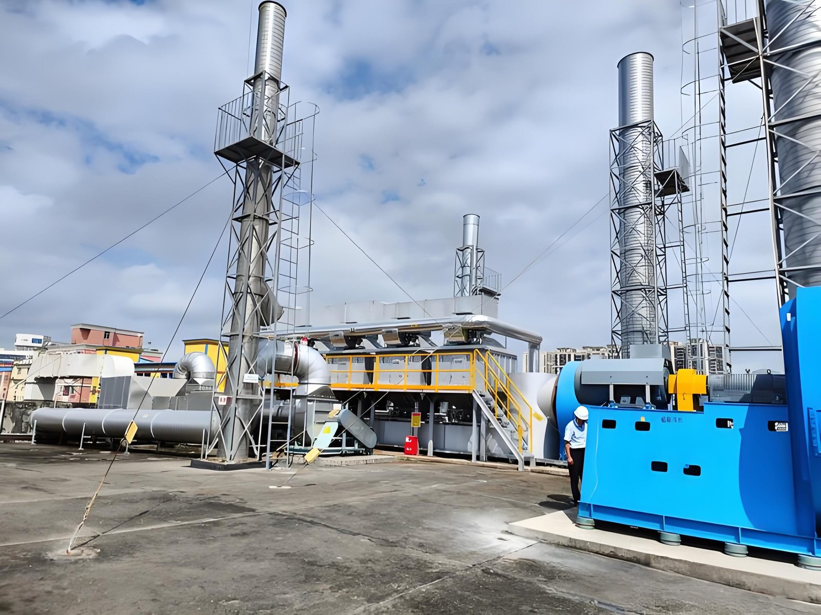
1. Treat the alarm as a timestamped event, not a component verdict
Start with the exact alarm text, controller event sequence and operating condition. A trip during pre-purge, at ignition, immediately after flame proof, after a period of stable operation, or during a production change may point to different evidence paths. One event code rarely tells the whole story.
Collect data from several comparable attempts or operating cycles where this can be done safely and without forcing resets. Preserve the original record before changing parts or settings. Useful evidence includes the burner-management sequence, combustion-air fan command and feedback, relevant pressure or airflow indication, fuel-train permissive status, ignition status, flame-signal trend where available, RTO chamber temperature trend, and recent process changes.
| Event pattern | Plausible explanations to investigate | Evidence before a repair decision |
|---|---|---|
| No stable flame proof after a normal start request | Combustion-air path issue, ignition/fuel issue, detector/viewing issue, sequence or permissive issue | Time-aligned sequence record; approved checks of air, fuel, ignition and detector conditions |
| Flame is proved, then drops out intermittently | Airflow disturbance, unstable combustion condition, optical contamination/vibration, wiring or power issue, process-related chamber condition | Flame-signal trend, fan status, operating state, fault timing and physical condition under approved access |
| Trips occur after weather, duct, filter or fan changes | Changed inlet condition, air-path restriction, fan/damper/control change, pressure reference issue | Compare current and baseline air-path configuration and matched operating data |
| Multiple resets are needed before it runs | A transient condition is being masked, not necessarily cured | Review lockout history and cause before further reset attempts; follow the installed reset policy |
| Only one burner or one mode is affected | Local burner train, detector alignment/view, wiring, local air path or logic input | Compare equivalent components and command/feedback paths using OEM-approved methods |
Do not turn this table into a fault codebook. It is a way to organize evidence and reduce unnecessary parts replacement.
2. Confirm the combustion-air path before changing burner parts
An RTO burner needs the air path intended by its installed design. The relevant hardware can include the combustion-air fan, inlet screen or filter, ducting, damper or actuator, pressure switches/transmitters, burner windbox, chamber connection and control wiring. A problem in any of these can affect ignition, flame stability or a permissive.
First compare the affected event with a known-good operating period. Was the fan commanded to run? Did the command, run feedback and any installed permissive arrive in the expected order? Was a filter, inlet screen, duct, damper, VFD setting, fan belt, actuator, access door or nearby process connection changed? A signal that says a fan is commanded on is not proof of the air quantity, path integrity or pressure condition required by the burner design.
Approved field review may need to consider:
- fan rotation, condition, vibration and drive status;
- inlet blockage, filter loading, screens, duct damage or unintended restrictions;
- damper command, actual position and linkage condition;
- pressure-sensing line condition, reference point and switch/transmitter health;
- loose panels, access doors, leaks or changes that alter the intended air path; and
- the relationship between burner events and RTO flow-reversal or process-exhaust changes.
Do not infer a correct air-to-fuel setting from a generic article. The allowable air, fuel, pressure and sequence conditions are specific to the burner, fuel, chamber, controls and site approval. A qualified burner technician should use the installed documentation and approved instruments.
3. Separate a flame-scanner problem from a combustion problem
The flame scanner is part of the proof chain, but a weak or interrupted flame signal does not always mean the detector itself is defective. Depending on the installed technology and arrangement, the detector may be affected by its viewing path, lens/window condition, mounting, aim, heat exposure, vibration, cable integrity, electrical noise or controller input condition. A real combustion disturbance can produce the same signal loss.
Use the event timing to guide the review. A detector fault may show a signal inconsistent with the actual burner sequence or a repeatable issue related to vibration, heat or connection movement. An air/fuel or ignition issue may track start demand, fan/damper state, fuel-train status, chamber condition or process change. These are hypotheses to test through approved OEM procedures, not conclusions to make from an alarm screen.
For the detector path, record what can be observed safely and non-invasively: lens/window cleanliness, visible obstruction, bracket condition, cable routing and connector condition, evidence of heat damage, and whether the detector’s intended line of sight has changed. Do not clean, reposition, calibrate or replace a detector without the applicable lockout, cooldown and OEM instructions.
4. Read the entire ignition-and-flame-proving sequence
RTO burner systems use an installed sequence to establish safe combustion. Exact arrangements vary, but the diagnostic discipline is consistent: identify the first condition that did not occur as expected, rather than focusing only on the final lockout.
| Review point | Question for the installed documentation and event record | Why it matters |
|---|---|---|
| Start demand and permissives | Which conditions must be true before the sequence starts, and which one changed? | Prevents a downstream component from being blamed for an upstream inhibit |
| Pre-purge / air proof | Did the burner-management system receive the intended approved proof of the air path? | Distinguishes an air-path or proof-input issue from a failed ignition attempt |
| Ignition and fuel admission | What event is recorded at the point the system expects ignition and stable flame? | Helps locate whether the fault occurs before or after fuel/ignition action |
| Flame-signal behavior | Is the signal absent, unstable, delayed or lost after being proved? | Directs the review toward detector, combustion stability or electrical evidence |
| Post-flame operating state | Did the trip align with fan, damper, process, reversal or temperature changes? | Reveals a disturbance that a single start record may hide |
Ask for the original controller sequence and configuration from the owner/OEM rather than relying on a generic diagram. In particular, do not copy timer values, flame thresholds, switch setpoints or reset practices from another RTO.
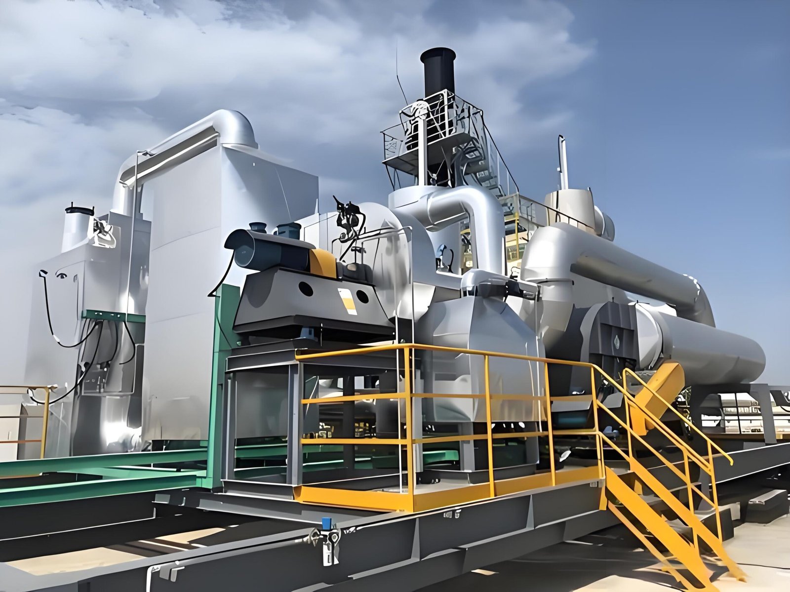
5. Include process and RTO operating context
Although the burner is local equipment, its operating context can matter. Process exhaust changes can affect RTO chamber behavior, draft and the system’s sequence of operating modes. Recent production changes, solvent substitutions, maintenance outages, fan work, duct modification, changes to bypass status, or unusual start-up/shutdown events deserve a place in the evidence package.
This does not mean a process change caused the burner trip. It means the team should not remove potentially relevant context before an engineering review. Align the burner event with available RTO temperatures, process-exhaust flow, fan/damper state, valve/reversal state and maintenance log. If an event only occurs in one operating phase, a matched comparison is often more useful than a long list of unrelated checks.
The U.S. EPA’s Regenerative Thermal Oxidizer fact sheet provides general background on RTO systems, retrieved 2026-07-22: https://www3.epa.gov/ttncatc1/dir1/frto.pdf. It does not provide a burner troubleshooting setting or site-specific operating instruction.
6. Build a corrective scope from evidence
A defensible scope identifies the observed condition, the evidence connecting it to a cause, the approved corrective action and the method for confirming the result. It should also record what remains uncertain. Examples of possible outcomes can include an instrument or wiring repair, detector-path correction, air-path repair, burner component service, a fuel-train investigation, an OEM logic/configuration review, or a process-side action. The article does not select among them.
Before approving a scope, request:
- The burner make/model, installed drawings and applicable OEM documentation.
- Exported event/alarm history with timestamps, not only a verbal description.
- A comparison between an affected event and a comparable normal event.
- Combustion-air fan command/feedback and the approved evidence for the relevant air path.
- Flame-detector type, approved maintenance history and allowed inspection findings.
- Fuel type, fuel-train drawings and any relevant qualified-service findings.
- Recent change log for process, ducts, fans, dampers, controls and maintenance.
- The approved isolation, restart and post-repair verification plan.
OSHA’s lockout/tagout guidance is a useful general reference for hazardous-energy control: https://www.osha.gov/lockout-tagout (retrieved 2026-07-22). Site and jurisdictional requirements remain controlling.
7. Avoid the shortcuts that create repeat faults
Repeated reset attempts can erase useful timing information and may contradict the installed safety procedure. Bypassing an air-proving device, flame detector, permissive or lockout is not a troubleshooting method for an operating plant. Likewise, changing fuel or air adjustments to “see if it holds” without qualified authorization can make the record less reliable and introduce risk.
The practical aim is simpler: preserve the original evidence, establish the first failed condition, review the correct system boundary, then have qualified personnel apply the OEM-approved correction. After work, compare the same signals under comparable operating conditions and update the maintenance record. That is more useful to a technical buyer than a generic claim that a burner has been “fixed.”
FAQ
Does a flame-scanner trip always mean the scanner is faulty?
No. The scanner may be affected by its viewing path, mounting, wiring, heat or controller input, but a real ignition, fuel, combustion-air or sequence issue can also prevent or interrupt flame proof. Use the timestamped sequence and OEM-approved checks to separate the possibilities.
Can a combustion-air fan issue cause an RTO burner lockout?
It can contribute if the installed burner-management system does not receive the intended air-path condition or if combustion stability is affected. The precise proof method and corrective action depend on the installed fan, controls, burner and approved documentation.
Is it safe to reset an RTO burner repeatedly after a flame-failure alarm?
Follow the installed OEM and site procedure. Repeated resets can obscure evidence and may not be permitted. A qualified review should determine why the sequence did not complete before restart.
What data should we send for a preliminary burner troubleshooting discussion?
Share the burner/RTO drawings where permitted, alarm sequence and timestamps, normal-versus-fault event records, fan/damper status, available temperature/process trends, recent changes, maintenance history and the applicable safety requirements. Do not share credentials or bypass safety controls to collect data.
Related SERNO engineering resources
- RTO Safety Interlocks and LEL Management: An Engineering Guide
- RTO Thermal Efficiency and Fuel Consumption: An Engineering Guide
- RTO Residence Time and Combustion Chamber Sizing: An Engineering Guide
- RTO System Maintenance Checklist for Industrial Plants
- SERNO RTO product overview
Need to structure an RTO burner troubleshooting review?
Send SERNO the available event history, installed drawings, process-exhaust range, combustion-air/fan information and description of recent changes. We can help structure the technical questions for an engineering discussion. Final service and operating decisions must be confirmed against the installed equipment, OEM documentation and site requirements.