 Request Proposal
What Makes Up a Complete RTO System? Look Beyond the Main Oxidizer
When a factory begins a VOC-treatment project, it is easy to ask for an “RTO.” But an RTO main unit is not the entire system.
A practical project has to move real exhaust from the process to a defined treatment route, manage the interfaces around that route, and provide a safe, maintainable operating boundary. What is included depends on the process, exhaust condition, site layout, and local requirements.
This guide is a plain-English scope map for first-time buyers. It is not a design, permit decision, safety assessment, or performance guarantee.
Start with the exhaust source and collection boundary
The system begins where exhaust is generated: a process hood, enclosure, dryer connection, tank vent, or another capture point. Duct branches and dampers then bring the proposed stream toward treatment.
Collection is not a background detail. Poor capture can leave emissions outside the system; uncontrolled branch changes can make the treatment duty unclear. Map sources, airflow estimates, operating periods, and normal versus non-routine events before treating the oxidizer as the whole project.
For a first data list, see VOC Exhaust Data Checklist Before RTO Quotation and What Are VOCs in Factory Exhaust?.
Conditional upstream protection: pretreatment is part of the scope conversation
Some streams can carry dust, fibers, mist, oil, resin, condensable material, or corrosive components. If those materials may reach the downstream equipment, the project may need upstream protection, different materials, changed collection, or a different treatment route.
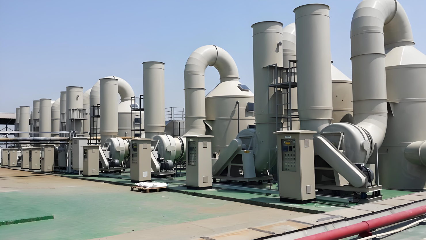
There is no universal pretreatment train. The right question is: what actually enters the duct under production, cleaning, changeover, and upset conditions? The answer should be based on process information and, where appropriate, qualified engineering review.
Read Which Industries May Be a Fit for RTO? for an early explanation of why an industry label alone cannot answer that question.
The RTO main unit: the treatment core, not the entire project
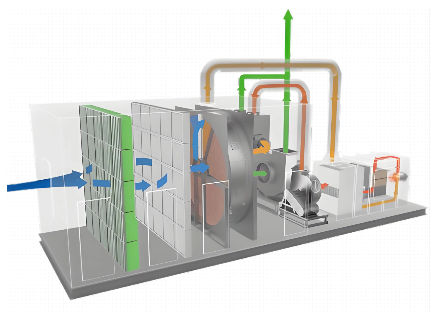
The regenerative thermal oxidizer is the treatment core of an RTO route. It commonly combines heat-recovery media chambers, a combustion section, flow-reversal equipment, insulation, access points, and instrumentation. Exact configuration is project-specific.
The main unit should be discussed alongside its incoming stream, operating schedule, utilities, controls, service access, and discharge path. A stand-alone equipment drawing cannot confirm that the surrounding system interfaces are workable.
Fans, ducting, and the discharge path connect the system
Fans and ductwork move the exhaust through the defined path. Their practical scope may include branch connections, transitions, supports, dampers, isolation points, and access for inspection. A stack or discharge arrangement completes the downstream path, subject to local and site-specific review.
These elements affect space, routing, noise considerations, maintenance access, and what is included in a supplier or site scope. See Industrial Exhaust Treatment Equipment for why dust, mist, acid gas, and VOC streams should not be assumed to share one route.
Controls, safety functions, and utilities make the scope operable
A treatment system needs an agreed control boundary. That may include a control panel, field instruments, operating statuses, alarms, interlocks, and interfaces to the factory process. The detailed logic and safeguards must be established for the actual project; they are not interchangeable from one line to another.
Utilities also need early confirmation. Depending on the route, that can include electrical supply, fuel, compressed air, drainage, foundations, and access around equipment. Listing an oxidizer without these interfaces can create scope gaps later.
A complete RTO system scope map
| System block | What to define early | Why it belongs in the same discussion |
|---|---|---|
| Capture and collection | Sources, hoods, ducts, branches, operating scenarios | Defines what is actually delivered to treatment |
| Conditional pretreatment | Dust, mist, oil, condensables, corrosive components | Helps protect the downstream route and clarify boundaries |
| RTO main unit | Process duty, configuration discussion, access needs | The treatment core must match the defined stream |
| Fan, duct, and stack path | Routing, supports, discharge arrangement, space | Connects the real process to and from the main unit |
| Controls and safeguards | Operating interfaces, alarms, project-specific logic | Makes the equipment operable within the plant boundary |
| Utilities and civil/site works | Power, fuel, air, drainage, foundation, access | Often affects schedule, responsibility, and budget scope |
The table is a scoping aid, not a standard equipment list or a compliance conclusion.
Five questions to ask before requesting an RTO proposal
- Where are all relevant exhaust sources, and which run at the same time?
- What is known about airflow, VOC materials, temperature, moisture, dust, mist, and unusual events?
- What collection, pretreatment, utilities, civil work, ducting, and stack items are already on site—and what must be included?
- Who will define the controls and operating interfaces with production equipment?
- Which local permit, testing, safety, and discharge requirements need qualified confirmation?
FAQ
Is the RTO main unit the same as a complete RTO system?
No. The main unit is central, but collection, stream conditioning where needed, duct/fan/stack connections, controls, utilities, and site works can be part of the broader project scope.
Does every RTO system need pretreatment?
Not necessarily. It depends on the actual inlet condition. The decision should follow a review of what could enter the collection system, not a generic diagram.
Can a supplier quote the RTO before all data are available?
An early budgetary discussion may be possible, but unknown data and unclear scope boundaries should be stated clearly. A final configuration needs project-specific review.
What should a buyer prepare first?
Prepare a process/source list, available material or SDS information, airflow estimates, operating schedule, photos or layout drawings, utility information, and notes about dust, mist, deposits, odor, or corrosion.
Build the system boundary before comparing equipment
SERNO can help structure an early discussion around the exhaust sources, stream data, collection boundary, conditional pretreatment, main treatment route, utilities, and site interfaces. Share the available project information through the SERNO RTO page or contact form. Final design and local-requirement decisions need project-specific engineering review.
Sources and retrieval note
For general background, consult the applicable local authority and qualified advisors. The U.S. EPA Stationary Sources of Air Pollution overview was checked on 2026-07-29 as general background only; it is not cited as a requirement outside the United States.