 Request Proposal
RTO Ceramic Media Fouling: How to Diagnose Rising Pressure Drop
When an RTO differential-pressure trend rises, the first conclusion is often simple: “the ceramic media is plugged.” Ceramic media can accumulate dust, sticky condensables, salts, corrosion products, or other deposits. But a changing pressure reading can also be caused by a new airflow condition, a restricted upstream device, a damper that is not in its intended position, a duct change, an impulse-line problem, or a transmitter with the wrong reference point.
For a plant team or technical buyer, the useful question is not “How soon can we replace the media?” It is: What evidence identifies the restriction, its likely mechanism, and the safest corrective scope? Replacing media without that evidence can leave the original contaminant source in place. Increasing fan speed without it can hide a developing restriction while adding energy use and mechanical load.
This is a general engineering guide. It does not prescribe a universal acceptable pressure drop, cleaning method, replacement interval, or isolation procedure. The installed RTO’s OEM documentation, site permit, approved safety review, and operating data remain controlling.
1. Why ceramic media matters to pressure drop
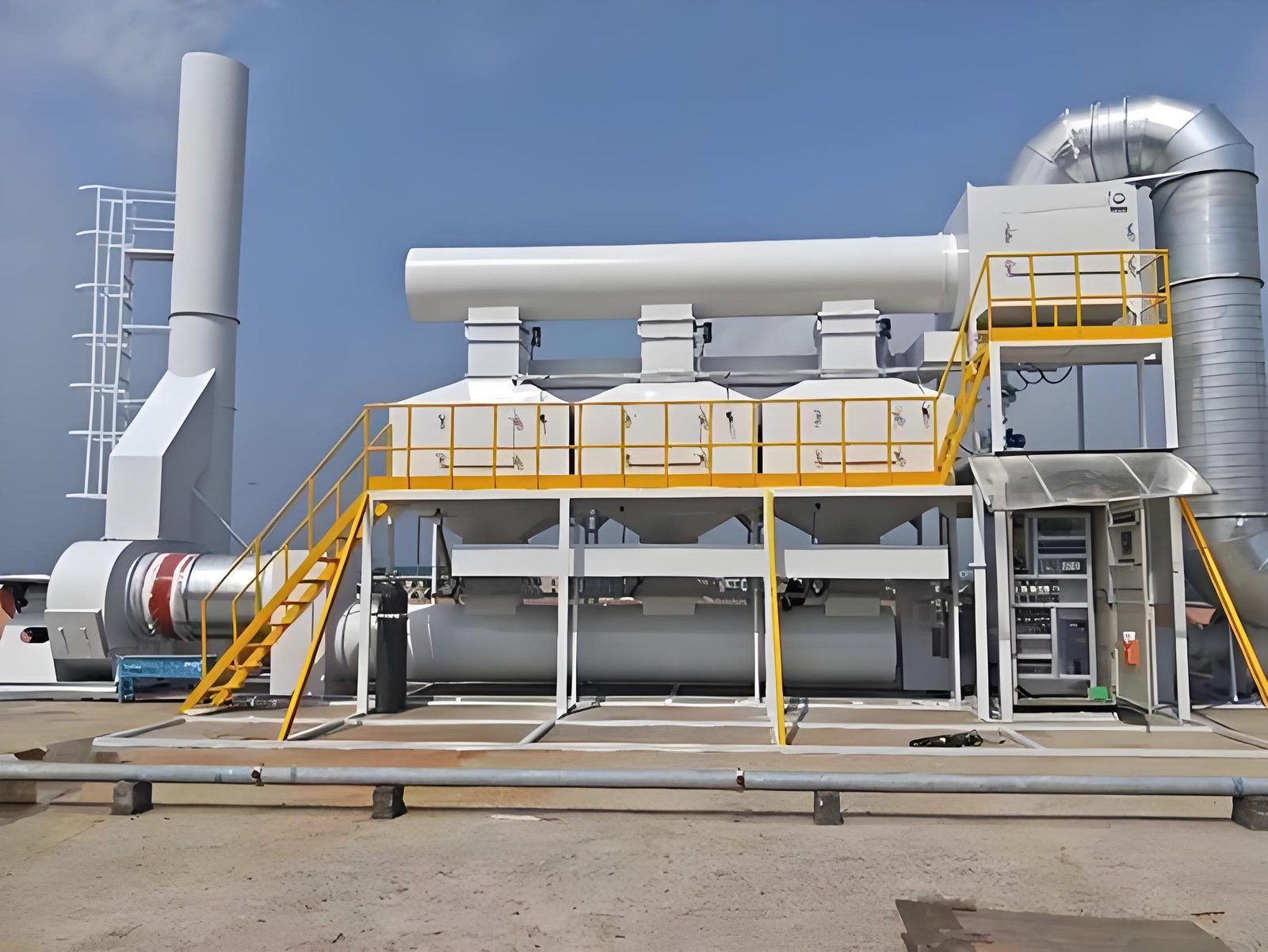
RTO ceramic media stores heat from treated gas and transfers that heat to incoming process exhaust during the next flow-reversal step. The media bed must provide a large heat-transfer surface while still allowing the intended gas flow to pass through. Its geometry, bed depth, support arrangement, gas distribution, contamination exposure, and switching configuration all affect resistance to flow.
Deposits can reduce open area or change the effective flow path. Fine dust may lodge in channels; sticky material can capture more particulate; condensed high-boiling compounds may bind particles together; corrosive or abrasive constituents can damage surfaces or supports. Those mechanisms are project-specific. A clean solvent exhaust does not behave like a stream carrying powder, paint mist, resin aerosol, silicon-containing compounds, acid gases, or intermittent wash-up vapour.
But ceramic media is only one part of the gas path. A differential-pressure signal may span a whole RTO section, not only a bed. Before diagnosing the media, confirm precisely where pressure is measured and what conditions existed when the reading changed.
2. First confirm that the trend is comparable
One pressure value has little meaning without its operating context. Compare readings taken at the same instrument points, fan mode, airflow range, valve state, production condition, and—where relevant—flow-reversal phase. A higher process airflow normally creates a higher pressure loss even when equipment condition is unchanged.
Build a time-aligned evidence set before planning invasive work:
| Evidence | Compare | Why it matters |
|---|---|---|
| Differential pressure | Same taps, range, zero check, and reversal phase | Separates a real trend from a reference or transmitter issue |
| Airflow and fan data | Actual flow, speed, damper position, current/power, static pressure | Shows whether a changed operating point explains the reading |
| Bed/chamber temperatures | Comparable points across several cycles | May reveal uneven flow or a bed behaving differently from its counterpart |
| Process record | Product, solvent, batch, cleaning, dust/mist source, uptime | Identifies a new contaminant or loading condition |
| Valve and bypass status | Command, feedback, travel alarms, manual overrides | Checks whether gas is following the intended path |
| Maintenance history | Filter changes, duct work, pretreatment issues, prior deposits | Links the trend to a plausible mechanism |
Trend at a resolution that can see complete operating cycles. Daily averages may obscure a cycle-linked restriction or a signal that shifts only when a valve state changes. Conversely, do not diagnose an RTO from one abnormal shift; capture comparable operation and record unusual process events.
3. Separate ceramic fouling from other restrictions
An RTO pressure-drop increase can originate upstream, inside the unit, or downstream. The following table is not a fault codebook; it helps direct the next evidence check.
| Observed pattern | Plausible explanations | Evidence before approving work |
|---|---|---|
| DP rises with airflow and returns at lower flow | Normal system curve, changed fan setpoint, production expansion | Compare matched airflow conditions and fan operating point |
| DP is high across all operating modes | Restricted filter, duct, silencer, stack path, transmitter/reference issue | Walk down the full approved pressure path; inspect instrument impulse lines and recent duct changes |
| One bed or reversal state differs repeatedly | Local media fouling, distribution issue, valve position/travel issue, local sensor issue | Align DP, valve command/feedback, temperature, and reversal timing |
| DP rose after a process/material change | New dust, mist, condensable or corrosive carryover | Review material list, collection points, pretreatment performance, and sampling/inspection evidence |
| Pressure signal is noisy or implausible | Plugged/leaking impulse lines, condensate, loose fitting, damaged transmitter | Verify instrument condition and zero/reference using the approved site method |
This sequencing protects both the plant and the procurement decision. If a clogged prefilter or altered duct branch is the root cause, media replacement will not correct it. If the media is contaminated, the upstream source and any missing pretreatment should be addressed with the media scope.
4. Check the inlet and pretreatment boundary
RTO media is not a general-purpose dust collector or mist eliminator. The project’s inlet boundary should be reviewed whenever a deposit is suspected. Ask what reaches the RTO in normal operation, at start-up/shutdown, during cleaning, and after any process change.
Items to review include:
- dust, powder, fibre, pigment, spray overspray, or abrasive particulate;
- oil mist, plasticizer, resin, adhesive, or other sticky aerosol;
- high-boiling or condensable VOC components and cold duct sections that can create carryover;
- acid-gas, sulfur, halogen, silicon, or other constituents that may affect material selection or deposit behaviour;
- filters, cyclones, mist separators, duct drains, hoods, and collection velocities; and
- new production lines, changed recipes, solvent substitutions, or temporary bypasses.
Do not infer chemistry from appearance alone. A dark layer, white deposit, or glazed surface can have several causes. If the approved site procedure allows sampling, document the location, operating condition, chain of custody, and analysis method before selecting cleaning chemicals or replacement media. Any sample or inspection activity must follow the site’s approved cooldown, isolation, access, and exposure controls.
5. Inspect the gas path and media bed safely
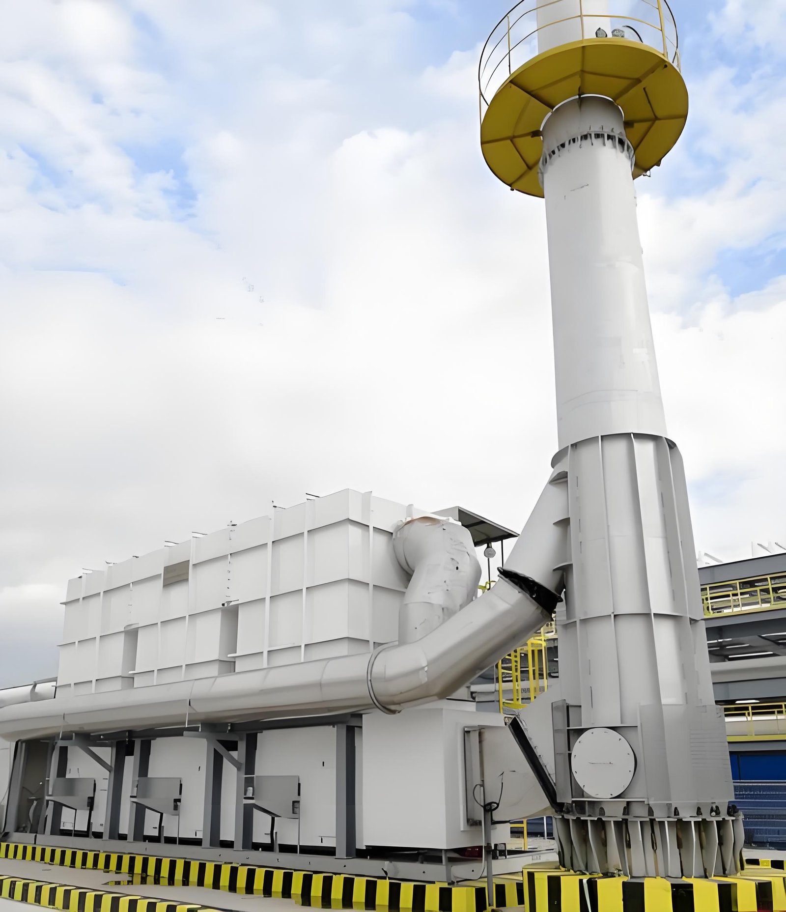
Physical inspection should be planned only after the evidence points to an internal restriction and the owner approves the work. The exact requirements for lockout/tagout, cooldown, confined-space entry, elevated work, gas testing, respiratory protection, and waste handling are site-specific. This article cannot authorize access to an RTO chamber or duct.
An approved inspection scope may need to check:
- media surface condition, channel openness, evidence of bridging, erosion, collapse, or foreign material;
- bed depth, levelness, support grids, retaining hardware, and distribution plates;
- nearby transitions, expansion joints, ducts, dampers, and purge paths for restrictions or displaced insulation;
- valve travel and actual gas-path configuration during the affected operating state;
- access-door seals and pressure taps; and
- representative documentation: location-marked photos, dimensions, deposit description, and an operating-data snapshot.
Avoid a “clean everything” scope until the deposit mechanism is understood. Aggressive mechanical cleaning can damage fragile media or supports; an unsuitable wash can create secondary contamination or corrosion. The equipment supplier’s media specification and the site’s waste/disposal controls should be reviewed before a method is chosen.
6. Use data after the intervention—not just before it
Whether the action is instrument repair, duct correction, pretreatment improvement, controlled cleaning, partial media repair, or media replacement, repeat the same measurement method under comparable operating conditions. Preserve the pre-work evidence and record the changed condition.
A useful close-out record includes:
- The observed symptom and its time-aligned data.
- The confirmed restriction or other root cause, including evidence and uncertainties.
- The scope performed and materials used.
- Any upstream process or pretreatment correction.
- Post-work pressure, airflow, temperature, valve-state, and analyzer checks taken under comparable conditions.
- Updated drawings, maintenance history, inspection triggers, and spare-parts information.
This record is more valuable than a generic statement that the RTO is “clean.” It creates a baseline for the next shift in trend and helps an engineering buyer compare a proposed repair scope with the actual failure mode.
7. Do not use fan changes as a substitute for diagnosis
Higher fan speed can restore flow temporarily, but it may also raise energy use, noise, duct velocity, and mechanical load. It does not remove deposits or correct a restricted path. Likewise, a stable fan current does not prove the media is clean; fan response depends on the whole system curve and control arrangement.
The earlier SERNO guide on RTO pressure drop and fan sizing addresses design selection and component budgeting. This diagnostic guide addresses a change from a proven operating baseline. In either case, compare suppliers and corrective actions on the same stated airflow, pressure basis, process condition, and system boundary.
8. A practical buyer checklist before approving a media scope
Before placing an order for cleaning, media, a fan modification, or an outage service, ask for the following in writing:
- Which pressure points and airflow conditions established the problem?
- Is the reading compared with a valid historical baseline at equivalent operating conditions?
- Which upstream/downstream restrictions and instrument faults were excluded?
- What evidence connects the observed deposit or restriction to the proposed work?
- What inlet contaminant, process event, or pretreatment gap is being corrected to prevent recurrence?
- What media specification, support-system checks, handling method, and waste controls apply?
- What post-work measurements will confirm the result, and under what process conditions?
- Which assumptions remain unverified and require owner/OEM review?
General RTO context is available in the U.S. EPA’s Regenerative Thermal Oxidizer fact sheet, retrieved 2026-07-21. It is background information, not a performance guarantee or maintenance instruction for a specific installation.
FAQ
Does a higher RTO pressure drop always mean ceramic media is plugged?
No. It may be caused by higher airflow, a changed fan/damper state, a restriction elsewhere in the gas path, a valve-path issue, or an instrument/reference problem. Compare matched operating data and inspect the approved system boundary before concluding that the media is fouled.
Can ceramic media be cleaned instead of replaced?
Possibly, but the decision depends on the media type, deposit chemistry, structural condition, support system, equipment manufacturer guidance, and approved safety/waste controls. Cleaning should not be selected before identifying the deposit mechanism and confirming that the media remains suitable for service.
What process conditions commonly create media-fouling risk?
Dust, powder, mist, sticky aerosols, condensable material, corrosive constituents, and inadequate collection or pretreatment can all contribute. The relevant risk depends on the actual exhaust composition, temperature profile, and operating events—not only the industry name.
Should we increase fan speed when the pressure trend rises?
Only after the owner’s engineering review. Fan changes may mask a restriction and alter energy use or equipment loading. First establish whether airflow changed, where the restriction is, and whether the operating point remains within the installed equipment’s approved envelope.
What data should be sent for a preliminary RTO diagnostic discussion?
Provide historical and current differential pressure, airflow, fan speed/current, temperature trends, valve/bypass status, process and material changes, exhaust composition, pretreatment details, photos from any approved inspection, and the installed P&ID/O&M information where shareable.
Related SERNO engineering resources
- RTO Pressure Drop and Fan Sizing: An Engineering Guide
- RTO System Maintenance Checklist for Industrial Plants
- RTO Valve Leakage: Diagnosing Outlet VOC Spikes and Heat Loss
- VOC Exhaust Data Checklist Before RTO Quotation
- SERNO RTO product overview
Need to review a changed RTO pressure-drop trend?
Send SERNO the matched operating data, exhaust composition, pretreatment details, equipment drawings, and a description of any recent process change. We can help structure the technical questions for an RTO diagnostic or corrective-scope discussion. Final recommendations must be confirmed against the installed system and site requirements.