 Request Proposal
RTO Fan VFD Operating Point: Verify Airflow Before Changing Frequency
A variable-frequency drive makes an RTO exhaust fan adjustable, but the displayed frequency is not an airflow measurement. Two systems running at the same hertz can deliver different flow because dampers, filters, duct resistance, process openings, gas density, fan condition, and production simultaneity are different.
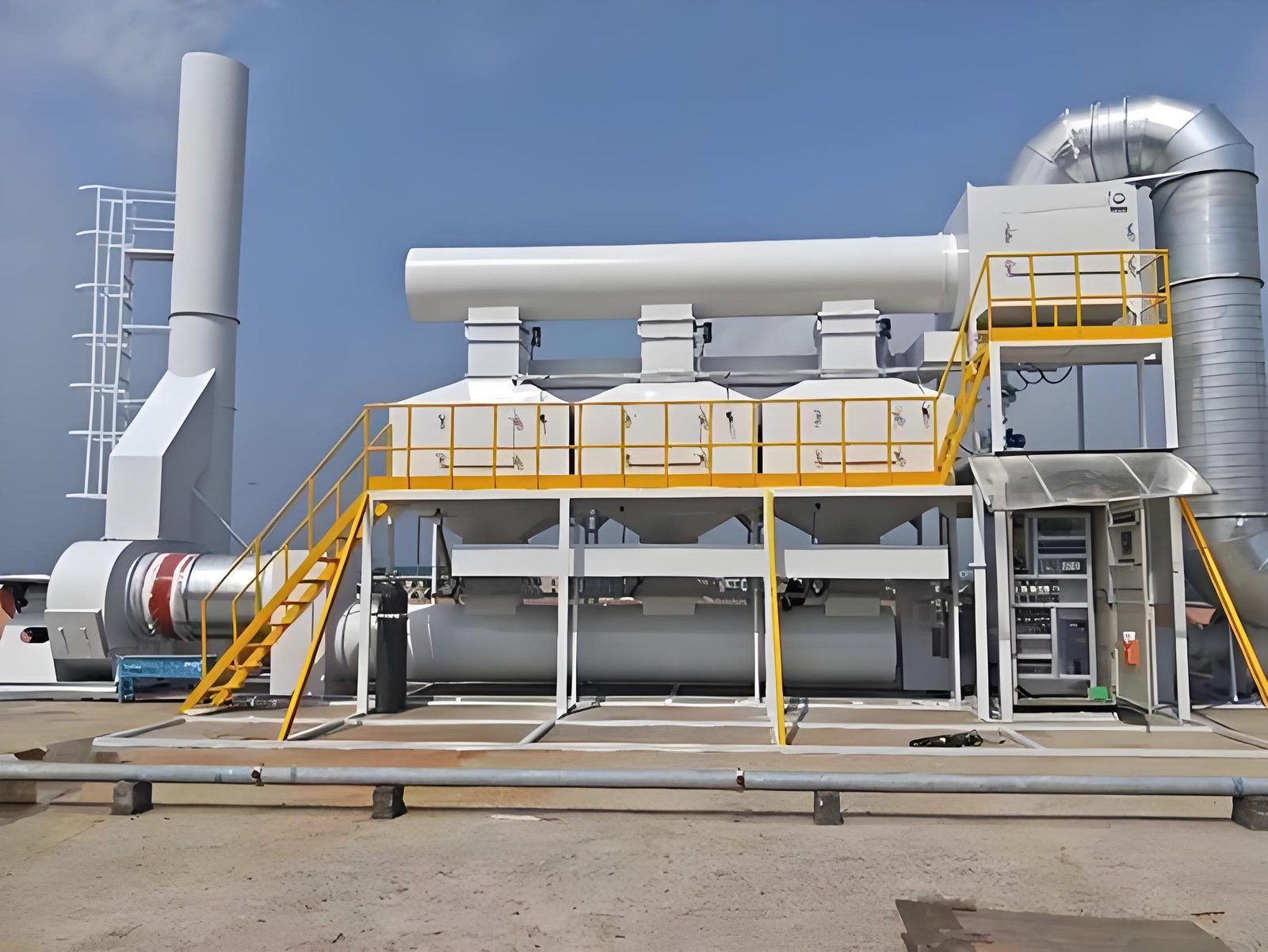
Changing frequency without recording the operating context can move a problem rather than solve it. Too little extraction may weaken source capture. Too much can increase energy use, entrain unwanted air, disturb ovens or booths, raise duct velocity, and shift the oxidizer load. This guide explains the evidence an industrial team should assemble before accepting or changing an RTO fan operating point. Final limits must come from the approved fan curve, motor data, process design, control philosophy, and site safety procedures.
1. Define the Required Duty Before Reading the VFD
Start with the service the fan must provide: which exhaust sources are open, which production lines can run together, required capture conditions, design flow at stated reference conditions, and the pressure needed to overcome the connected system resistance.
Record whether the fan is on the clean or dirty side of the treatment train and whether the control target is duct pressure, hood pressure, airflow, oven balance, or another verified process variable. A frequency setpoint is only a means of reaching the required duty; it is not the duty itself.
2. Record the Complete Operating Context
An operating-point record should identify the production state at the same time as the measurements. Include active sources, product or coating family where relevant, open doors or bypasses, filter condition, damper positions, ambient conditions, exhaust temperature, and any maintenance or process change.
Avoid comparing a full-production reading with a reduced-shift reading as though the duct network were unchanged. Mark temporary hoses, isolated branches, added extraction points, and manual damper adjustments. These details often explain why the same frequency produces a different pressure or flow.
3. Measure Airflow and Pressure at Defined Locations
Use suitable, maintained instruments and documented measurement locations. A single velocity reading near an elbow, damper, transition, or fan connection may not represent the average duct velocity. Where a traverse is required, use the applicable site or engineering method and record the duct dimensions, temperature, pressure, and reference basis.
Pressure readings also need context. State whether each value is static, velocity, or total pressure and identify the upstream and downstream locations. Trend filter differential pressure separately from overall system resistance. Never infer capture performance solely from fan inlet suction if branch conditions are unknown.
4. Use the Fan Curve and System Curve Together
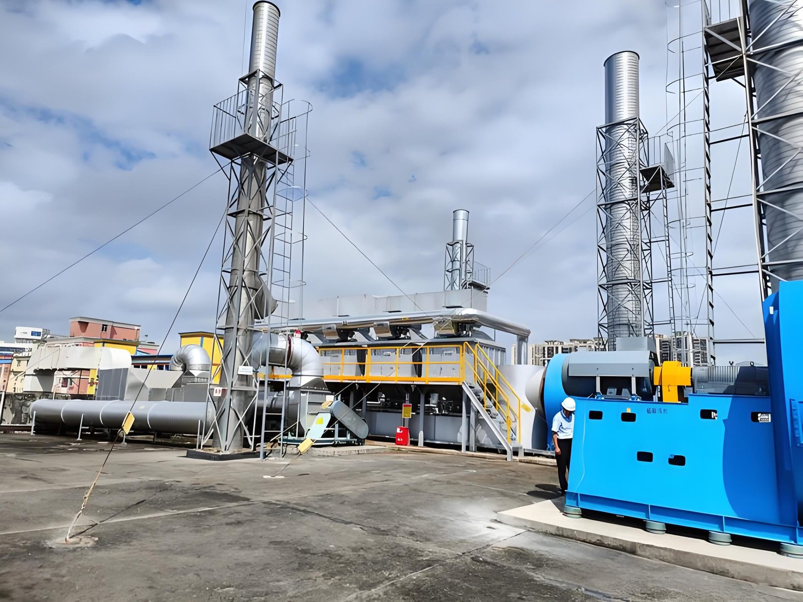
The fan operating point is where the fan capability and system resistance meet. Review the approved fan curve for the actual wheel, rotation, speed range, gas density, and configuration. Confirm that the selected point remains inside the documented operating envelope and does not overload the motor.
Fan affinity relationships can support preliminary reasoning for the same system near similar conditions: flow changes approximately with speed, pressure with speed squared, and power with speed cubed. They are not a substitute for measurements when dampers move, filters load, branches change, gas properties vary, or the fan is operating outside the assumptions.
5. Check Motor, VFD, and Mechanical Evidence
Record frequency, commanded speed, actual speed if available, motor current, power, voltage, drive alarms, bearing condition, and vibration together. Compare them with approved nameplate and supplier limits without inventing a universal acceptance value.
A low current does not prove adequate airflow, and a high current does not identify the cause by itself. Unexpected load can come from excessive flow, density changes, mechanical condition, control settings, or an incorrect fan configuration. Confirm minimum-speed, acceleration, cooling, resonance-avoidance, and interlock requirements from the equipment documentation.
6. Confirm Capture and Process Stability
The correct fan point must work at the sources. Observe or measure the approved capture indicators at hoods, booths, ovens, enclosures, and room boundaries. Check for odor escape, visible migration where a safe approved method exists, door interference, excessive inward draft, process temperature disturbance, or unstable burner and pressure-control behavior.
Do not increase fan speed as the first response to every capture complaint. A closed damper, disconnected branch, blocked filter, damaged hood, open access door, poor make-up air, or changed production layout may be the real cause.
7. Build an Operating-Point Evidence Table
| Evidence group | Record together | Decision question |
|---|---|---|
| Production state | active lines, source simultaneity, doors and bypasses | Does the test represent the intended operating case? |
| Air network | damper positions, filter DP, branch status, make-up air | Is the network configuration known and repeatable? |
| Flow and pressure | method, location, reference conditions, measured values | Is required capture achieved with traceable measurements? |
| Fan and drive | frequency, speed, current, power, alarms | Is the duty inside approved fan, motor, and VFD limits? |
| Mechanical condition | vibration, bearings, noise, flexible connection | Is mechanical behavior stable at this point? |
| Treatment process | inlet state, relevant temperatures and pressure | Does the RTO remain stable as airflow changes? |
| Release record | date, instruments, personnel, deviations, approval | Can the operating point be reproduced and audited? |
8. Control Setpoint Changes and Revalidate
Treat a permanent frequency change as a controlled change. Record the previous setpoint, reason, authorized range, affected recipes or modes, test sequence, results, and rollback condition. Protect critical parameters with the plant’s access-control and change-management process.
After adjustment, repeat the relevant capture, airflow, pressure, motor-load, vibration, and treatment-process checks at the defined production cases. One successful moment is not enough if the plant has multiple operating modes. Establish a baseline that future teams can compare with the same measurement locations and operating context.
FAQ
Does 50 or 60 Hz mean the fan is delivering design airflow?
No. Frequency indicates the drive command, not verified flow. Actual duty depends on fan configuration, system resistance, gas conditions, damper positions, filter loading, and the connected sources.
Can fan frequency be increased to fix poor hood capture?
Only after checking the cause and approved operating limits. Poor capture may come from hood geometry, branch isolation, filter blockage, make-up-air imbalance, open doors, or a changed process rather than insufficient fan speed.
Which readings should be stored with a VFD setpoint?
Store the production state, branch and damper configuration, airflow and pressure measurement details, filter differential pressure, temperature, fan speed or frequency, motor load, vibration, capture observations, and any deviations.
Should affinity laws be used to choose the new setpoint?
They can support an engineering estimate when their assumptions are valid, but field measurements and the approved fan/system data are still required. Network changes and variable gas conditions can invalidate a simple speed ratio.
Professional CTA
If you are reviewing an RTO fan setpoint, retrofit, or proposal, SERNO can help structure the engineering questions around exhaust sources, airflow cases, pressure loss, fan selection, VFD control, capture evidence, and treatment-system stability. Share verified process data and available drawings for a technical discussion; final settings and limits must be confirmed for the specific installation.