 Request Proposal
RTO Fan Flexible Connection Inspection: Check Duct Loads Before Restart
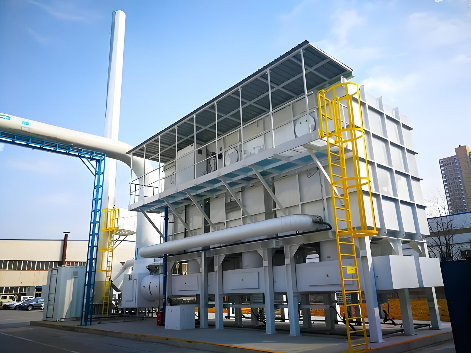
An induced-draft fan is often connected to an RTO duct by a fabric or metallic flexible element. Its purpose is limited: accommodate specified movement, isolate part of the vibration transmission, and tolerate normal thermal growth. It is not a structural support, an alignment correction, or a substitute for properly restrained ductwork.
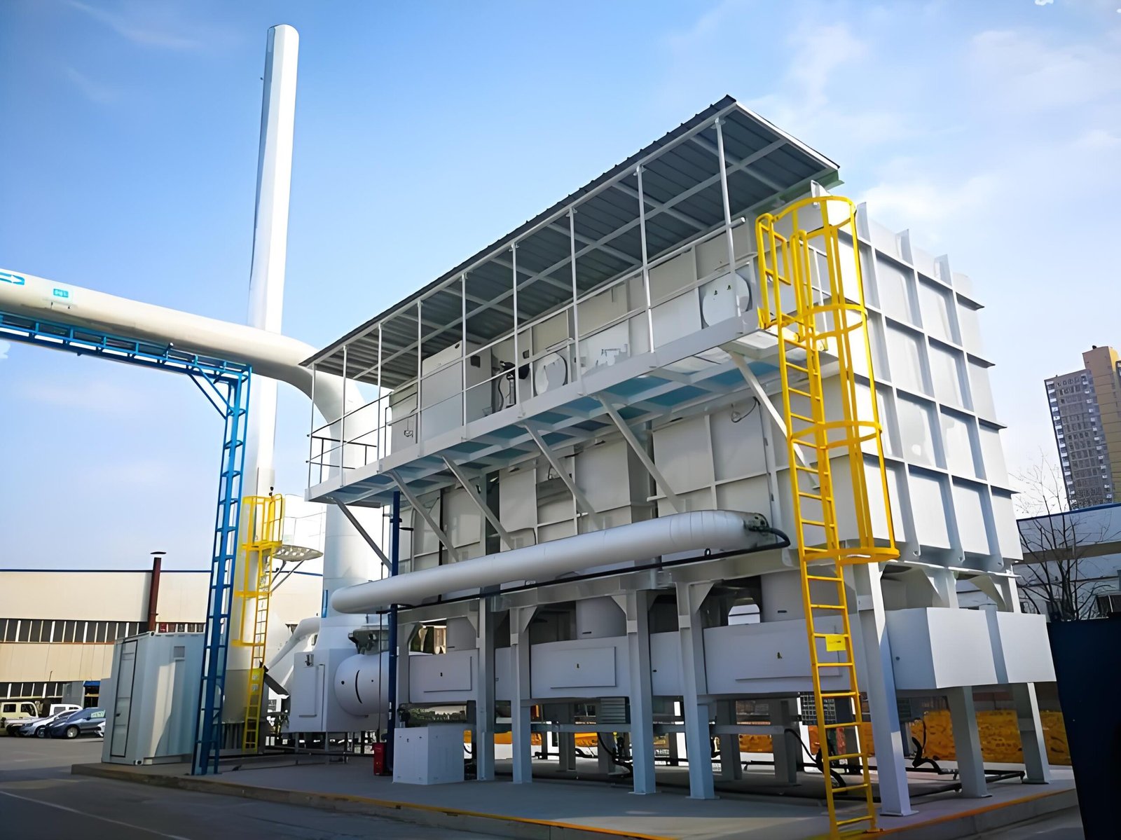
When the connector wrinkles unevenly, pulls sideways, tears near a flange, or repeatedly loosens bolts, replacing the connector alone may only reset the failure clock. The inspection should determine what load the adjoining duct and supports are imposing on the fan connection. This guide provides a practical shutdown review for industrial buyers, maintenance teams, and engineers. Actual acceptance limits must come from the fan, connector, duct, and support documentation for the installed system.
1. Define the Connector’s Intended Movement
Start with the design basis rather than the damaged appearance. Identify the connector type, material, temperature rating, flow direction, installed face-to-face dimension, and permitted axial, lateral, and angular movement. Confirm whether an internal liner, flow sleeve, insulation blanket, or external restraint is part of the assembly.
Compare the approved drawing with the installed arrangement. A connector fitted shorter, longer, or more offset than its intended neutral geometry may already be consuming its movement allowance while the system is cold. Photograph the four sides with a scale before loosening anything.
2. Inspect the Fabric, Flanges, and Fasteners
With the exhaust train isolated, locked out, cooled, and verified safe under the plant procedure, inspect the full circumference. Look for:
- abrasion, pinholes, delamination, hardening, blistering, or heat discoloration;
- folds concentrated on one side and tension on the opposite side;
- damage close to bolt bars or flange corners;
- loose, missing, mismatched, or bottomed-out fasteners;
- gasket extrusion, uneven clamp pressure, and signs of gas leakage;
- contact between the flexible element and an internal liner or nearby steelwork.
Do not infer material fitness from appearance alone. If the process has changed, check the actual temperature, solvent composition, moisture, mist, and cleaning exposure against the connector supplier’s documented limits.
3. Check Cold Alignment Before Disconnecting the Joint
Record the fan inlet or outlet flange position relative to the adjoining duct flange. Useful evidence includes gap measurements at several clock positions, centerline offset, flange parallelism, connector face-to-face dimension, and photographs from fixed reference points.
If the joint is disconnected, the duct should not jump, drop, rotate, or spring sideways. Unexpected movement indicates stored load or inadequate support. Plan temporary support before releasing bolts; a flexible connector must never become the item holding the duct in place.
4. Review Duct Supports, Guides, and Anchors
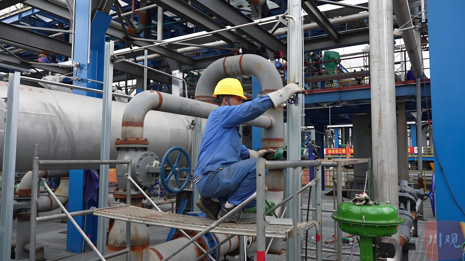
Follow the load path away from the connector. Inspect support shoes, hangers, springs, guides, anchors, structural steel, and base fasteners. Search for loose anchors, cracked grout, bent brackets, polished rub marks, elongated holes, missing slide plates, seized guides, or insulation preventing intended movement.
The question is not simply whether supports exist. Ask whether each support still performs its assigned function when the duct is cold, hot, under fan suction, and exposed to wind or maintenance loads. Field modifications, added silencers, dampers, access platforms, or heavier insulation can change the original load path.
5. Separate Thermal Movement from Installation Misalignment
Thermal growth should move through the intended guides and expansion features. Installation misalignment is a cold geometric error. The two can produce similar connector distortion but require different corrections.
Use available cold and operating measurements to compare positions. If distortion appears only when hot, review thermal movement, guides, and anchors. If the connector is already offset when cold, review erection alignment and support elevation. If movement follows fan speed or damper position, investigate aerodynamic loading and pressure pulsation as well as mechanical support.
6. Build a Restart-Release Evidence Table
| Inspection item | Evidence to record | Release question |
|---|---|---|
| Connector identity | type, material, drawing/reference, installed dimension | Is it the approved part for temperature and process exposure? |
| Flexible element | four-side photos, wear and leakage observations | Is it intact and free from damaging contact or pre-tension? |
| Flanges and bolts | gap, parallelism, bolt condition, clamp pattern | Are flanges aligned and uniformly clamped? |
| Duct support | support ID, condition, elevation, free/sliding status | Does the duct remain independently supported? |
| Guides and anchors | position, looseness, rub marks, unauthorized changes | Can thermal growth follow the intended path? |
| Fan base interface | base bolts, grout, soft-foot or movement observations | Is the fan position stable without duct forcing? |
| Cold run readiness | guards, tools cleared, temporary supports removed | Is the train safe for a controlled first run? |
| First-run baseline | vibration, noise, pressure, temperature, connector movement | Does behavior remain within approved limits and baseline expectations? |
7. Verify the Interface During a Controlled Restart
After corrective work, complete the plant’s pre-start safety review. Observe the connector from a safe position during the controlled first run. Watch for rapid inflation or collapse, flutter, rubbing, abnormal movement, leakage, new noise, and changes as dampers or fan speed move through the planned operating range.
Record fan vibration, relevant pressure readings, bearing condition, connector position, and operating state together. A single measurement without airflow, temperature, damper position, and production context is difficult to compare later. Stop and investigate if the connector or duct moves in a way that was not anticipated by the approved design.
8. Clarify Responsibility Before the Next Outage
Define who owns connector specification, spare supply, duct-support inspection, fan alignment, insulation removal and reinstatement, lifting and temporary support, first-run monitoring, and final release. These boundaries often span the fan supplier, duct contractor, RTO integrator, maintenance team, and plant engineering.
For procurement or retrofit work, request interface drawings and allowable connection loads rather than accepting “flexible joint included” as a complete scope description. The commercial boundary should state who verifies that the installed duct does not impose unacceptable forces or moments on the fan.
FAQ
Can a flexible connector correct duct misalignment?
It may physically accommodate limited movement within its approved range, but it should not be used to conceal poor cold alignment or carry structural duct load. Correct the load path and geometry first.
Should the connector be tight when the system is cold?
Not by assumption. The required neutral geometry depends on the connector design and expected thermal movement. Compare the installed dimension and offset with approved documentation.
Why does a replacement connector fail again?
Repeated failure can result from unresolved misalignment, unsupported duct weight, seized guides, excessive movement, heat or chemical exposure, abrasion, pressure pulsation, or incorrect installation. Preserve evidence before removing the failed part.
What should be measured after restart?
At minimum, record the operating state, relevant pressures and temperatures, fan vibration, abnormal noise, leakage, and visible connector movement. Use the equipment documentation and plant procedures to define limits.
Professional CTA
If you are comparing a new RTO package or reviewing a fan-duct retrofit, SERNO can help organize the interface questions: exhaust conditions, fan operating range, connector material, support arrangement, thermal movement, access, spares, and restart evidence. Share drawings and verified process data for an engineering discussion; final limits must be confirmed for the specific installation.