 Request Proposal
RTO Burner Airflow Ratio Verification: Separate Combustion-Air Drift from VOC Load Changes
When an RTO shows a different chamber temperature, oxygen reading, fuel signal, or pressure trend, plant teams often start with the process exhaust. That can miss a simpler cause: combustion-air flow or damper position has drifted. The correct diagnostic question is not “What is the burner setpoint?” but “What air-to-fuel condition existed at the same verified process load?”
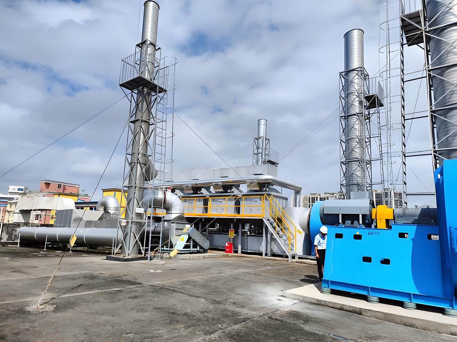
This guide lays out a measurement boundary for checking burner airflow ratio without inventing a universal ratio. Final limits must come from the approved burner package, OEM instructions, fuel train design, combustion safeguards, and site procedures.
1. Define the comparison case
Select a stable operating window and document which chambers, burners, bypasses, and exhaust sources were active. Record production state, solvent or coating family where relevant, source capture status, inlet VOC measurement if available, chamber temperature, oxygen, fuel command, and fan operating point. A reduced-shift case cannot be compared directly with a full-production case.
2. Map the combustion-air path
Identify the combustion-air fan, filters, inlet louver, manual and control dampers, flexible connections, burner registers, and any dilution or purge-air tie-ins. Record measurement locations and whether the value is a calibrated flow, a pressure proxy, or only a command signal. A damper percentage is not proof of delivered airflow.
3. Verify instruments before interpreting trends
Check calibration status, impulse lines, transmitter zero, temperature and pressure compensation, and the time alignment of historian tags. Confirm that airflow units and reference conditions are consistent. If a flow element is outside its validated range, label the reading as indicative rather than quantitative.
4. Build the ratio evidence table
| Evidence row | Record | Why it matters |
|---|---|---|
| Combustion-air flow | Instrument, location, units, reference basis | Confirms delivered air rather than command position |
| Fuel flow or valve position | Meter/tag and stable time window | Defines the paired fuel condition |
| Burner oxygen or flue-gas oxygen | Location, temperature basis, analyzer status | Shows the combustion response, not just the input |
| Air and fuel pressure | Upstream/downstream points | Reveals restriction or regulator drift |
| Damper/register position | Feedback plus physical inspection status | Detects linkage or feedback mismatch |
| Process/VOC state | Active sources and measured trend | Prevents combustion drift being blamed on load |
Compare rows at the same timestamp and under the same approved firing mode. Do not calculate a ratio from unrelated historian averages.
5. Separate air-path faults from VOC-load changes
If fuel and combustion-air signals move together while process conditions remain stable, investigate control logic, regulator behavior, and burner sequencing. If combustion-air pressure changes while the command remains constant, inspect filters, louvers, fan condition, and dampers. If oxygen changes with stable air and fuel evidence but VOC loading changes, review the oxidizer heat-release balance and sampling boundary instead of immediately retuning the burner.
6. Use safe adjustment gates
Any adjustment should have a written setpoint range, interlock status, flame-safeguard readiness, responsible person, rollback condition, and post-change observation window. Never bypass purge, flame failure, high-temperature, or pressure protections to obtain a “clean” test. Record the pre-change state so the result remains attributable.
7. Specify the procurement and service scope
When requesting support, define whether the supplier must measure airflow, verify burner registers, inspect filters and dampers, validate analyzer signals, or retune control parameters. Ask for raw readings, instrument references, operating cases, and acceptance criteria—not only a final ratio number.
FAQ
Is there one correct RTO burner airflow ratio?
No. The acceptable relationship depends on burner design, fuel, firing mode, excess-air requirements, safeguards, and the OEM-approved operating envelope.
Can oxygen alone prove the burner ratio?
No. Oxygen is a response indicator affected by leakage, dilution, sampling location, temperature, and process conditions. Pair it with airflow, fuel, pressure, and operating-state evidence.
Should a higher VOC reading trigger more combustion air?
Not automatically. Confirm the measurement boundary, heat-release trend, chamber temperature, and approved control philosophy before changing combustion settings.
Practical CTA
SERNO can help teams define an RTO combustion-air verification scope, measurement points, and evidence checklist for a retrofit, commissioning review, or troubleshooting visit. Share the burner type, fuel, available tags, and operating cases for a technically bounded review.