 Request Proposal
Rotor RTO Pretreatment Evidence: Prove Mist and Dust Control Before the Zeolite Rotor
A zeolite rotor concentrator is often discussed as the heart of a Rotor RTO system. In practice, the equipment in front of the rotor determines what reaches its adsorbent surface. Paint mist, oil aerosol, dust, condensable vapor or a process-side change can create fouling, pressure-drop growth, carryover or an unstable operating window. A filter symbol on a P&ID is not proof that the pretreatment boundary is adequate.
This guide shows plant teams and buyers how to define and evidence the pretreatment boundary before approving a Rotor RTO design, retrofit or corrective scope. It does not prescribe a filter grade or guarantee rotor life. The OEM, responsible engineer and site procedures control final selection, access, sampling and change-out.
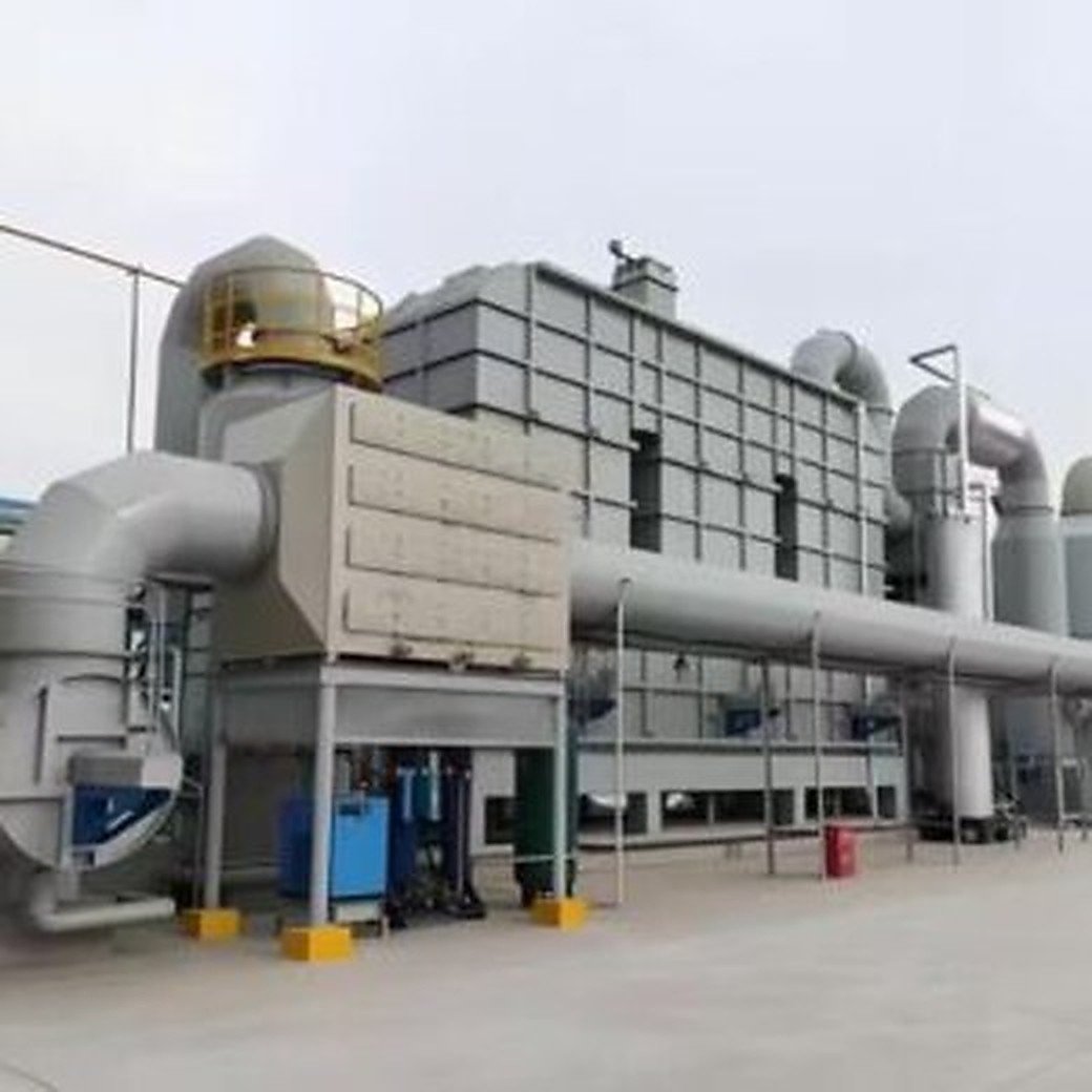
1. Start with a source-to-rotor contaminant map
List every source that can connect to the rotor inlet, including temporary headers, cleaning vents, maintenance exhaust and future production branches. For each source, record the process, material family, expected airflow pattern and credible contaminant forms. A source map should distinguish continuous, batch and abnormal releases rather than averaging them into one generic VOC number.
At minimum, ask:
- Can the source produce liquid droplets, sticky aerosol, dust, fibers or condensable vapor?
- What changes when the recipe, supplier, coating, resin or cleaning chemical changes?
- Can a bypass, drain, low point or failed damper send material around the intended pretreatment?
- What happens during startup, shutdown, upset or a fan trip?
- Which streams are allowed to connect, and who authorizes a new connection?
The map is the design basis for the pretreatment train. Without it, a supplier can size a filter while leaving the contaminant question undefined.
2. Define the pretreatment train by function
Describe each stage by the risk it controls, not only by its equipment name. A typical review may include source capture, coarse filtration, fine filtration, mist elimination, cooling or condensation control, drains, access sections and differential-pressure instrumentation. The exact arrangement depends on the exhaust chemistry and the selected rotor.
| Function | Evidence to request | Buyer question |
|---|---|---|
| Capture and segregation | Source list, damper logic, hood or header drawings | Can an abnormal source bypass the protection boundary? |
| Dust and particulate control | Filter type, housing details, change-out method, DP range | What indicates loading before carryover occurs? |
| Mist and aerosol control | Droplet/aerosol basis, eliminator arrangement, drain path | Where does liquid go, and how is re-entrainment prevented? |
| Condensate management | Temperature profile, low points, drains, heat tracing if applicable | Can condensate reach the rotor during cold or transient operation? |
| Monitoring | DP tags, alarm limits, sampling points, inspection access | Which reading triggers action and who owns it? |
Functional language exposes missing interfaces more clearly than a list of component names.
3. Treat differential pressure as a trend, not a single number
Pressure drop across a filter or mist eliminator is useful only when the measurement boundary is clear. Record the clean baseline, airflow or fan condition, temperature, instrument status and the date of each reading. A high value may indicate loading; a sudden low value can also indicate a damaged element, bypass or a disconnected impulse line.
Create a simple log with:
- Section and instrument tag.
- Airflow or fan speed at the time of reading.
- Clean/reference condition and current value.
- Alarm or action threshold defined by the responsible engineer.
- Filter, drain or cleaning action taken.
- Rotor-inlet observation and downstream consequence, if any.
Do not invent a universal replacement threshold. The correct limit depends on the selected hardware, flow range, dust or mist loading and the supplier’s instructions.
4. Check drains, low points and re-entrainment paths
Mist control is incomplete if collected liquid has nowhere controlled to go. Inspect low points, drain legs, traps, collection vessels and access doors under an approved procedure. Confirm that drains remain usable during the operating temperature range and that a blocked or full vessel cannot push liquid back into the airflow.
Review the conditions that can create re-entrainment:
- excessive face velocity or poor flow distribution;
- a drain without a suitable seal or collection arrangement;
- fan transients that disturb settled liquid;
- cold sections where vapors condense unexpectedly;
- maintenance panels or gaskets that leak around the intended path.
Photographs and inspection notes should identify location and operating context. A wet surface alone does not prove rotor damage, but it is a reason to preserve evidence and review the path.
5. Verify transient and abnormal cases
The pretreatment boundary must be reviewed during more than the design steady state. Ask what happens when production starts, a batch changes, a fan ramps, a source is isolated, or a process upset sends an unusual concentration or aerosol load toward the header.
| Case | What to verify | Record |
|---|---|---|
| Startup | Filter and mist-control readiness before source admission | Release checklist and DP baseline |
| Recipe or material change | New aerosol, condensable or dust risk | Change record and source review |
| Fan trip or low flow | Drainage, cooling and rotor protection logic | Alarm sequence and restart gate |
| High-loading event | Isolation or diversion response | Time, source, actions and inspection |
| Planned shutdown | Clean-air purge and exposed-surface condition | Outage work pack and photos |
These cases connect pretreatment design to operations. The Rotor RTO shutdown preparation guide covers the later outage stage; this article focuses on the evidence before contaminants reach the rotor.
6. Make inspection access part of the scope
A pretreatment device that cannot be inspected safely will eventually become an assumption. The scope should show access doors, lighting, drain access, lifting or change-out clearance, sample points and the location of DP instruments. Clarify whether the buyer, OEM or maintenance contractor owns inspection and consumables.
During a permitted inspection, separate observations from conclusions. Record filter condition, deposits, liquid evidence, gasket condition, drain status and instrument health. Link each observation to a source, date and operating case. Do not open hazardous equipment or remove elements outside the approved isolation and permit process.
The complete RTO system-scope guide is useful when checking that access, controls, drains and interfaces have not disappeared between the process design and the quotation.
7. Questions to ask before approving a pretreatment scope
- Which contaminant forms and source changes are included in the design basis?
- Which stages protect against dust, mist, condensables and accidental liquid carryover?
- What are the clean/reference DP values, alarm logic and inspection response?
- How are drains sealed, monitored and protected from re-entrainment?
- What happens during startup, fan trips, batch transitions and abnormal loading?
- Which consumables, access platforms, lifting aids and spare elements are included?
- What evidence will be recorded before the rotor is released for production gas?
- Which assumptions require a process sample, pilot test or OEM confirmation?
A low equipment price can conceal missing access, drains, instruments or change-out responsibility. Normalize the scope before comparing bids.
FAQ
Why does pretreatment matter for a zeolite rotor?
Pretreatment controls material that could foul, wet, obstruct or otherwise stress the rotor. The specific risk depends on the process and rotor design; the source map and operating evidence should define it.
Is a rising filter pressure drop always bad?
Not automatically. A trend can indicate loading, but instrument faults, airflow changes, damaged elements or bypass conditions can produce misleading readings. Compare like-for-like conditions and follow the supplier’s limits.
Can a mist eliminator replace a dust filter?
They address different risks. A mist device is not automatically a particulate-control stage, and the correct combination depends on particle and droplet characteristics, flow and the rotor supplier’s design basis.
What should be documented after a process change?
Update the source and material map, review aerosol/condensable risks, confirm pretreatment capacity and controls, and record the approved release evidence before reconnecting the source.
Should buyers specify only a filter efficiency percentage?
No. A useful scope also defines contaminant form, airflow range, housing/access, DP monitoring, drains, change-out responsibility and transient cases. A percentage without the test basis can be misleading.
A practical next step for plant teams
Before requesting a Rotor RTO pretreatment quotation, assemble a source-and-material map, recent DP and drain records, transient operating cases, photographs from approved inspections and the list of planned process changes. SERNO can review that boundary with a buyer and identify which assumptions need supplier confirmation. OEM instructions, site permits and the responsible engineer remain controlling.