 Request Proposal
RTO Safety Interlocks and LEL Management: An Engineering Guide
RTO safety is not a single sensor, a single alarm, or a percentage copied from a previous project. It is an engineered chain: understand the exhaust stream, prevent an unsafe combustible mixture from reaching the oxidizer, prove that the equipment is ready to operate, and move the plant to a defined safe state when a critical condition is lost.
For EHS teams and technical buyers, the practical question is not simply “Does the RTO have LEL monitoring?” It is: Which conditions are measured, what assumptions sit behind each setpoint, what action follows a fault, and how is that action validated before start-up? This guide explains the questions that belong in an RTO specification and quotation review. It is general engineering information, not a replacement for a HAZOP, process safety review, or the requirements adopted by the authority having jurisdiction.
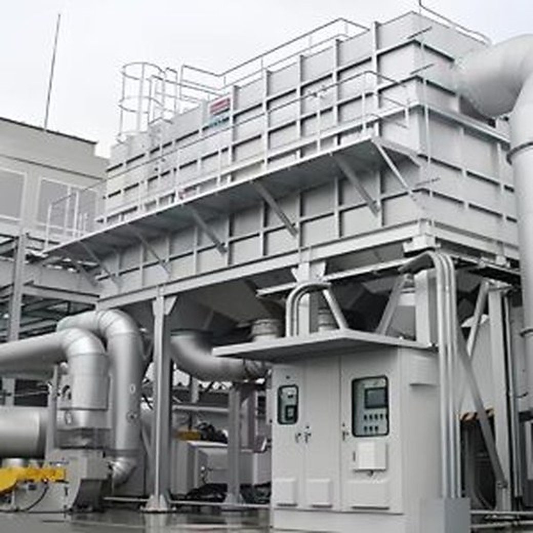
1. Why combustible-mixture management comes before equipment sizing
An RTO oxidizes VOCs at elevated temperature. That makes it effective for suitable industrial exhaust, but it also means the inlet stream must be characterized for flammability, concentration variation, oxygen content, temperature, pressure, mist, dust, and possible contaminants. A nominal average concentration is not enough. Batch charging, solvent changeover, line cleaning, fan stops, and duct interactions can create short-duration peaks that are not visible in a monthly production average.
LEL—the lower explosive limit—is a property of a combustible material in a stated oxidant and temperature condition. Real exhaust can contain several solvents, humidity, inert gases, and changing oxygen levels. The mixture behaviour can differ from a single-component data sheet. A design team should therefore establish the relevant worst credible operating cases and the analytical method, sampling location, response time, and calibration plan used to monitor them.
The correct operating limit is project-specific. It must be set by the applicable code, the selected safety philosophy, and competent process-safety review. A supplier brochure or generic post cannot establish a safe setpoint for a particular plant.
2. The safety layers an RTO buyer should expect
Good RTO safety design uses layers so that no single ordinary control failure becomes a hazardous event. The exact architecture varies by jurisdiction and process, but a quotation should distinguish the following functions.
| Safety layer | Engineering purpose | Buyer review question |
|---|---|---|
| Process design | Keeps normal exhaust composition and flow within the approved envelope | What normal, peak, startup and upset cases were used? |
| Detection | Identifies relevant concentration, flow, temperature, pressure, valve or flame conditions | Which instruments are safety-critical, and where are they located? |
| Permissives | Prevents start-up unless required conditions are proven | Which conditions must be true before fan, burner and valves can run? |
| Trips/interlocks | Takes a defined action when a hazardous condition is detected | Does each trip specify alarm, shutdown action, reset method and cause? |
| Mechanical/process safeguards | Provides robust backup where controls alone are insufficient | Are isolation, relief, ventilation, dilution, flame protection or bypass arrangements included where the review requires them? |
| Procedures and proof testing | Maintains the design over time | Who owns calibration, functional testing, change management and records? |
An HMI screen is not proof of an independent safety function. Ask the engineering team to identify the instruments, logic solver or safety relay where used, final elements, diagnostic coverage, test intervals, and failure response. The appropriate independence and performance requirements should come from the project risk assessment, not a marketing claim.
3. What an LEL monitoring design must define
“LEL monitor included” is incomplete wording. A useful specification identifies the analyser technology and its limitations, the sample conditioning arrangement, the location of the sample point, expected transport delay, alarm/trip philosophy, calibration gas and frequency, and how failed or out-of-range readings are handled.
Sampling points must represent the stream that can enter the oxidizer. A point too far upstream can miss downstream solvent addition, leakage, or dilution; one too close to a turbulent branch may give unstable readings. Heated lines, filtration, condensate control, and a sample-flow failure alarm may be required depending on the stream. Some gas mixtures, mists, or compounds have limitations with a particular sensor technology. The analyser supplier and process-safety team should review cross-sensitivity and poisoning risks before final selection.
The logic should define at least four states: healthy reading within the approved envelope; alarm; trip; and analyser/system fault. Treating a failed analyser as a healthy zero reading is not an acceptable assumption. The specified safe action may be to stop VOC introduction, isolate a source, maintain or stop extraction according to the process design, purge, or shut down the RTO in a controlled sequence. The action must be designed with the production process so that it does not create a separate exposure or emission problem.
4. Start-up permissives and purge are part of the safety function
Before ignition or introduction of VOC-bearing gas, an RTO normally needs a defined sequence that confirms the equipment and gas path are ready. The final sequence must follow the approved design and applicable standard, but a buyer can ask whether it accounts for the following:
- correct fan status and proven airflow/draft;
- required damper and isolation-valve positions;
- a completed, measured purge of the relevant volume before burner ignition;
- burner management system checks such as flame supervision and fuel-valve proving where applicable;
- acceptable temperature/pressure conditions and no active emergency stop;
- healthy safety instruments and communications required by the approved logic;
- confirmation that the process stream is within its approved composition envelope before admission.
Purge volume and duration cannot be chosen from a rule of thumb without considering the actual connected volume, flow path, fan performance, damper positions and possible dead legs. The sequence should be documented so commissioning personnel can verify it, and so maintenance changes do not silently invalidate the calculation.
5. Interlocks need clear cause-and-effect documentation
For every major trip, request a cause-and-effect matrix. It should show the initiating signal, alarm level, automatic action, annunciation, shutdown sequence, reset conditions, manual action required, and any signal that must remain available after the trip.
Typical causes to address in the project review include high combustible-gas indication, analyser fault, loss of extraction airflow, burner/flame fault, abnormal chamber temperature, high differential pressure where relevant to the configuration, critical valve-position discrepancy, emergency stop, and loss of required utility. The matrix should explain what happens to the VOC source, the RTO fan, fuel, inlet/outlet dampers, purge cycle, valve system and bypass—if a bypass exists. “System shuts down” is too vague for a purchase specification.
Avoid designing one trip in isolation. For example, stopping an exhaust fan can change the pressure balance of a process area; opening or closing a damper can affect dilution and the path to stack. The safe state needs to be evaluated across the RTO, duct network and production process.
6. Commissioning is where assumptions become operating evidence
Factory and site commissioning should verify both normal operation and safe response. A written test plan should list the instrument loop checks, calibration certificates, programmed setpoints under change control, interlock functional tests, burner-management tests, valve/damper travel checks, airflow verification, purge verification, alarm annunciation, emergency-stop response, and restoration procedure.
Testing should use approved methods that do not introduce combustible gas or create an unsafe condition. Simulation may be appropriate for some inputs; other checks need field confirmation of actual flow or device movement. Each test needs an acceptance criterion and a signed record. If any cause-and-effect action is changed after commissioning, repeat the affected proof test and update drawings, logic narratives and operator procedures.
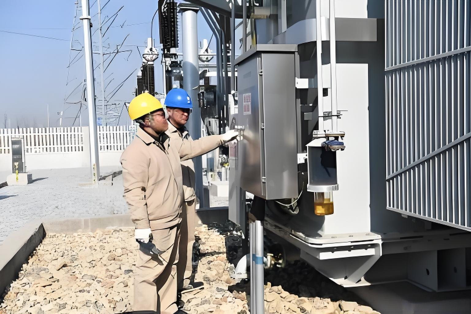
7. Procurement checklist: questions to send with an RFQ
Send enough process information for the supplier and safety team to engineer the system rather than guess. The following checklist helps start the conversation:
- Normal, maximum, minimum and upset exhaust airflow, temperature and pressure.
- VOC species, concentration range, batch/cleaning peaks, oxygen content, humidity, dust, mist and corrosive components.
- Lower-explosive-limit data and mixture assessment provided or validated by qualified parties.
- Process operating modes, simultaneous sources, changeover sequence and future expansion plans.
- Applicable local codes, permit requirements, hazardous-area classification and owner safety standards.
- Required shutdown philosophy for the process and treatment system.
- Requested instrument list, cause-and-effect matrix, P&ID, electrical classification, control narrative and commissioning test records.
- Ownership of calibration, proof testing, spare sensors/parts and management of change after handover.
The goal is not to turn a quotation into a safety case. It is to make the quotation transparent enough that the owner can compare safety scope, engineering assumptions and lifecycle responsibilities fairly.
8. Common mistakes to prevent during operation
The most persistent safety weaknesses are often introduced after the equipment is delivered: a new solvent is used without review, an analyser calibration is deferred, a nuisance trip is bypassed, a duct branch is added, or a software setting is changed without updating the cause-and-effect matrix. These are management-of-change issues, not simply maintenance issues.
Keep an approved operating envelope and train operators on what happens outside it. Investigate repeated alarms; do not normalise them. Preserve calibration and functional-test records. When a process change may affect VOC concentration, oxygen, airflow, temperature, contaminants or connected volume, bring the RTO engineer and safety owner into the review before the new condition is operated.
FAQ
Is one fixed percentage of LEL safe for every RTO?
No. A setpoint must be determined for the actual mixture, process, equipment configuration, safety strategy, and the code adopted for the project. This article intentionally does not prescribe one universal number.
Does an LEL analyser alone make an RTO safe?
No. It is one element in a system that also needs valid process data, appropriate sample design, permissives, shutdown logic, purge/ignition controls, mechanical safeguards as required, procedures and proof testing.
What should happen if an LEL analyser fails?
The approved safety philosophy must define this. The failure needs to be detected, alarmed and brought to a defined response; it should not be treated as a healthy measurement. The response must be coordinated with the process and emission-control design.
Can an RTO safely accept any solvent stream if it has dilution air?
No. Dilution is a design measure that requires validated flow, mixing, control and failure analysis. Solvent composition, peak concentration, oxygen content, temperature, contaminants and operating variability still require review.
Which documents should be requested before acceptance?
At minimum, request the P&ID, instrument list, control/sequence narrative, cause-and-effect matrix, electrical/hazardous-area information where applicable, approved operating envelope, commissioning test record, calibration/proof-test plan, and operating/maintenance manuals.
Related SERNO engineering resources
- Regenerative Thermal Oxidizer product overview
- VOC exhaust data checklist before quotation
- RTO pressure drop and fan sizing guide
- RTO residence time and combustion chamber sizing
- Industrial VOC treatment application references
Need an RTO safety-scope review?
Send SERNO the exhaust-flow range, VOC composition and concentration range, process modes, existing safety requirements and local project location. We can help define the engineering information needed for an RTO/Rotor RTO proposal. Final safety design and code compliance must be verified for the specific project by competent parties and the applicable authority.