 Request Proposal
SERNO Knowledge Center
RTO Pressure Drop and Fan Sizing: An Engineering Guide
Pressure drop is one of the least visible—but most expensive—design variables in a regenerative thermal oxidizer project. It determines fan static pressure, motor size, electrical consumption, airflow stability and the amount of negative pressure that reaches the production line. If it is underestimated, the plant may lose capture velocity or production capacity. If it is overestimated, the owner pays for an unnecessarily large fan, motor, variable-frequency drive and electrical supply.
This engineering guide explains how to build an RTO pressure-drop budget, translate it into fan duty, evaluate operating points and compare supplier quotations on an equal basis. It is intended for plant engineers, EHS teams, project managers and buyers preparing an industrial VOC abatement project.
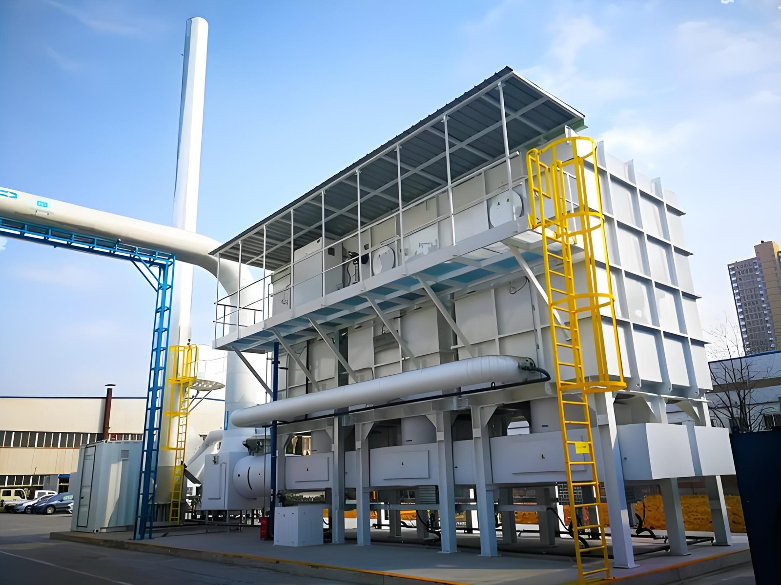
What pressure drop means in an RTO system
Pressure drop is the loss of total pressure as exhaust gas moves through hoods, ducts, filters, dampers, valves, heat-recovery media, the oxidation chamber, stack and other components. It is normally expressed in pascals (Pa), millibars or inches of water column. The induced-draft fan must supply enough pressure rise to overcome the complete system resistance at the required airflow.
The fan does not only serve the oxidizer skid. In many projects, it also maintains negative pressure in the collection network. Therefore, the correct design boundary starts at the process capture point and ends at the stack discharge. A quotation that lists only “RTO internal pressure drop” is not yet a complete fan-sizing basis.
Build a pressure-drop budget before selecting the fan
A practical pressure-drop budget separates fixed equipment losses from field duct losses. Each item should have a clean-design value, a normal operating value and, where relevant, a dirty or end-of-service value. The following ranges are illustrative only; actual values depend on airflow, geometry, media type and gas properties.
| System element | Typical design concern | What must be confirmed |
|---|---|---|
| Capture hood and branch duct | Insufficient velocity or poor balancing | Required capture velocity and simultaneous line operation |
| Main duct and fittings | Long runs, elbows, transitions and high velocity | Route, diameter, equivalent length and gas temperature |
| Filter or pretreatment | Pressure rises as dust or mist accumulates | Clean and dirty differential pressure alarm points |
| Isolation and control dampers | Partially closed dampers add large local losses | Operating position, leakage class and actuator logic |
| RTO switching valves | Rapid flow-path changes create pulsation | Valve area, switching sequence and sealing condition |
| Ceramic media beds | Velocity, fouling and media geometry dominate loss | Media depth, open area, gas loading and fouling allowance |
| Stack and silencer | Exit velocity and acoustic equipment add resistance | Stack diameter, height, silencer and rain-cap design |
Add the losses at the same design airflow, then apply a justified margin. Do not add a large arbitrary percentage to every item and then add another large fan margin; stacked conservatism can move the selected fan far from its efficient operating region.
Airflow changes pressure drop nonlinearly
For a fixed duct and equipment geometry, pressure drop is approximately proportional to the square of flow rate. A useful estimating relationship is:
ΔP₂ ≈ ΔP₁ × (Q₂ / Q₁)²
If a system has 3,000 Pa resistance at 40,000 m³/h, increasing flow to 50,000 m³/h does not increase resistance by only 25%. The estimated resistance becomes 3,000 × (50,000 / 40,000)² = 4,688 Pa, about 56% higher. This is why apparently small airflow additions from future production lines can require a major fan and duct review.
Gas density also matters. Fan curves are commonly based on standard inlet density, while hot process exhaust has lower density. Suppliers should state whether airflow is actual cubic metres per hour or normalized flow and identify the temperature, pressure and density used for fan selection.
Ceramic media pressure drop and fouling allowance
Ceramic heat-recovery media is central to RTO efficiency, but it also creates resistance. Smaller hydraulic passages can provide high heat-transfer surface area while being more sensitive to particulate, condensable material and high-boiling organic deposits. Media depth, face velocity and flow distribution must be considered together.
An RTO designed for clean solvent vapor should not automatically be applied to exhaust containing paint mist, resin aerosol, silicon compounds or sticky condensables. Pretreatment may be required. Otherwise, pressure drop can slowly increase, fan speed rises to hold airflow, power consumption increases and eventually the system may no longer maintain the required capture rate.
Specify differential-pressure measurement across each media bed where practical. Trend values under comparable airflow and temperature conditions. A rising trend is more useful than one isolated reading because pressure naturally changes with flow, valve position and gas density.
Switching valves, pressure pulsation and process stability
Multi-chamber RTOs periodically reverse flow through ceramic beds. During the switching sequence, pressure can fluctuate. Poorly coordinated valves, excessive leakage, undersized headers or aggressive switching can transmit pressure pulses back toward coating, printing or drying equipment.
The control design should maintain stable process negative pressure, not merely stable fan speed. Depending on the process, this can require a pressure transmitter in the main collection duct, a VFD speed loop, controlled valve overlap, a balancing damper or a small buffering volume. The supplier should explain expected pressure fluctuation and the measurement location used for control.
From pressure-drop budget to fan duty point
The minimum fan specification should include design airflow, required static or total pressure, inlet temperature, gas composition, density, corrosion considerations, expected turndown and allowable noise. The duty point is where the fan curve intersects the system resistance curve. Selection should remain in a stable and efficient region, with reasonable distance from surge or stall.
Motor power can be estimated from:
Electrical input ≈ Q × ΔP / (fan efficiency × drive efficiency)
For 50,000 m³/h (13.89 m³/s) at 4,500 Pa, with 72% fan efficiency and 96% drive efficiency, estimated input is 13.89 × 4,500 / (0.72 × 0.96) ≈ 90 kW. The installed motor may be larger to cover operating margin and site conditions, but this calculation provides a useful reasonableness check.
At 8,000 operating hours per year, even a 10 kW avoidable loss equals 80,000 kWh annually. Pressure-drop optimization should therefore be evaluated as lifecycle engineering, not only as a capital-cost exercise.
How to choose a reasonable design margin
A fan needs margin for manufacturing tolerances, field duct deviations, filter loading and future degradation. However, margin should be transparent. Ask suppliers to separate calculated resistance, fouling allowance and fan selection margin. A common mistake is selecting a motor for a hypothetical extreme while operating every day with throttled dampers. A properly controlled VFD usually provides a more efficient way to accommodate variation.
Future expansion should be treated as a defined scenario: future airflow, added duct length, additional pretreatment and expected operating schedule. Because resistance varies approximately with flow squared, “20% spare airflow” is not equivalent to “20% spare pressure” or “20% spare motor power.”
VFD control and the fan affinity laws
For the same fan and gas density, airflow is approximately proportional to speed, pressure to speed squared, and power to speed cubed. Reducing speed to 90% can reduce ideal power to roughly 73% of the original value. Real systems differ, but the relationship shows why VFD control can save substantial electricity when lines operate at partial load.
The control loop must still respect minimum exhaust velocity, chamber temperature, purge requirements and safety interlocks. Energy saving cannot override capture performance or explosion protection. Minimum and maximum fan speed, damper positions and alarm thresholds should be documented during commissioning.
Commissioning tests that should be recorded
- Measure airflow at each active branch and total main duct under agreed production scenarios.
- Record static pressure before and after pretreatment, fan, RTO media beds and stack components.
- Verify fan speed, motor current, VFD frequency, bearing vibration and inlet temperature.
- Test clean-filter and simulated dirty-filter conditions where possible.
- Trend main-duct pressure through several RTO valve-switching cycles.
- Confirm the process maintains capture velocity with all specified lines operating.
- Document the final damper positions and pressure-control setpoint.
How to compare RTO supplier quotations
Request a common pressure-drop schedule from every bidder. It should identify the design boundary, airflow basis, gas temperature, clean and dirty values, internal RTO loss, external duct allowance, selected fan duty, efficiency, absorbed power and motor rating. If two suppliers quote very different motor sizes, compare their assumptions before concluding that one design is more efficient.
Also clarify whether the fan is upstream or downstream of the oxidizer. An induced-draft arrangement can keep contaminated ductwork under negative pressure, but the fan may see hotter gas depending on heat recovery and system layout. Materials, shaft sealing, insulation and temperature rating must match the actual location.
Common engineering mistakes
- Using nominal airflow without distinguishing actual and normalized conditions.
- Ignoring dirty-filter or media-fouling pressure drop.
- Calculating only the RTO skid and excluding field ducts, hoods, silencers or stack losses.
- Oversizing the fan and wasting energy through permanent damper throttling.
- Placing the control pressure transmitter where valve switching makes the signal unstable.
- Adding production lines without recalculating the system curve.
- Comparing motor nameplate power instead of absorbed power at the guaranteed duty point.
FAQ
What is a normal pressure drop for an RTO?
There is no universal value. Chamber count, ceramic media, face velocity, valves, pretreatment and external ductwork all matter. The correct requirement is a documented component-by-component budget at the specified airflow and gas condition.
Should the fan be sized for clean or dirty filters?
The fan and motor should cover the agreed maximum operating resistance, including the defined dirty-filter condition. Normal control should operate closer to the clean or mid-life point without unnecessary throttling.
Why does RTO airflow fall after several months?
Possible causes include loaded filters, media fouling, deposits in ducts, a changing damper position, valve leakage or fan deterioration. Compare current differential-pressure, speed and motor-current trends with commissioning data.
Can a larger motor solve insufficient airflow?
Not by itself. The fan impeller, speed limit, system curve, duct velocity and mechanical ratings determine achievable airflow. Increasing motor size without checking the fan curve can create safety and reliability problems.
What data should be sent for fan selection?
Provide actual airflow by operating case, gas temperature, altitude, VOC and particulate characteristics, duct layout, pretreatment, required process pressure, stack details, turndown and future expansion scenario.
Need an RTO pressure-drop review?
Send SERNO your airflow, exhaust temperature, duct route, VOC composition, pretreatment requirements and operating schedule. Our engineers can help establish a practical pressure budget and equipment selection basis.