 Request Proposal
RTO Gas Distribution Verification: Diagnose Uneven Flow Before Changing Internals
An RTO can show uneven chamber temperatures, unstable pressure or inconsistent outlet readings without a failed ceramic bed. The apparent imbalance may begin upstream in the duct, at a switching valve, at an instrument tap or in the distribution zone. Before specifying new internals, map the actual flow path and collect measurements that can be compared at the same operating point and valve phase.
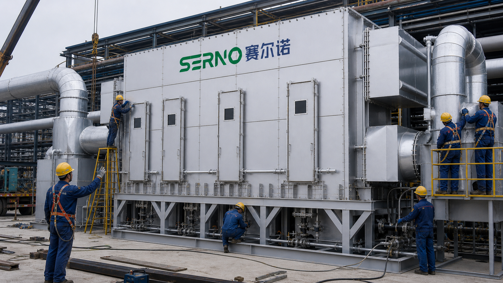
This is a general engineering investigation framework, not a claim about a particular SERNO installation. Site-specific acceptance limits belong in the approved design, operating procedure and applicable permit.
1. Define the operating case and flow boundary
Record production line states, fan speed, inlet flow estimate, VOC loading range, dilution and temperature. Identify every branch, isolation damper, bypass path, switching valve, chamber inlet, media bed and outlet. Mark where pressure and temperature are measured and where samples are taken. A comparison is weak if one chamber is measured during a different process load or switch phase.
2. Capture phase-aligned trends
Trend chamber inlet and outlet temperatures, differential pressures, valve position feedback, fan speed and alarms through multiple complete switching cycles. Keep timestamps and historian resolution visible. Separate the short transition interval from the stable portion of each phase; averaging both together can hide a recurring asymmetry. Check sensor calibration and impulse-line condition before interpreting a small difference. See the pressure instrument-line inspection guide.
3. Distinguish flow imbalance from measurement error
A plugged pressure tap, drifting thermocouple, changed sample location or delayed analyzer response can mimic distribution trouble. Verify instrument range, tapping orientation, sample line integrity and time alignment. If a reading changes only when a specific valve moves, inspect that valve’s travel and seal condition before blaming the bed. The bypass damper inspection guide outlines a related boundary check.
4. Inspect accessible distribution hardware
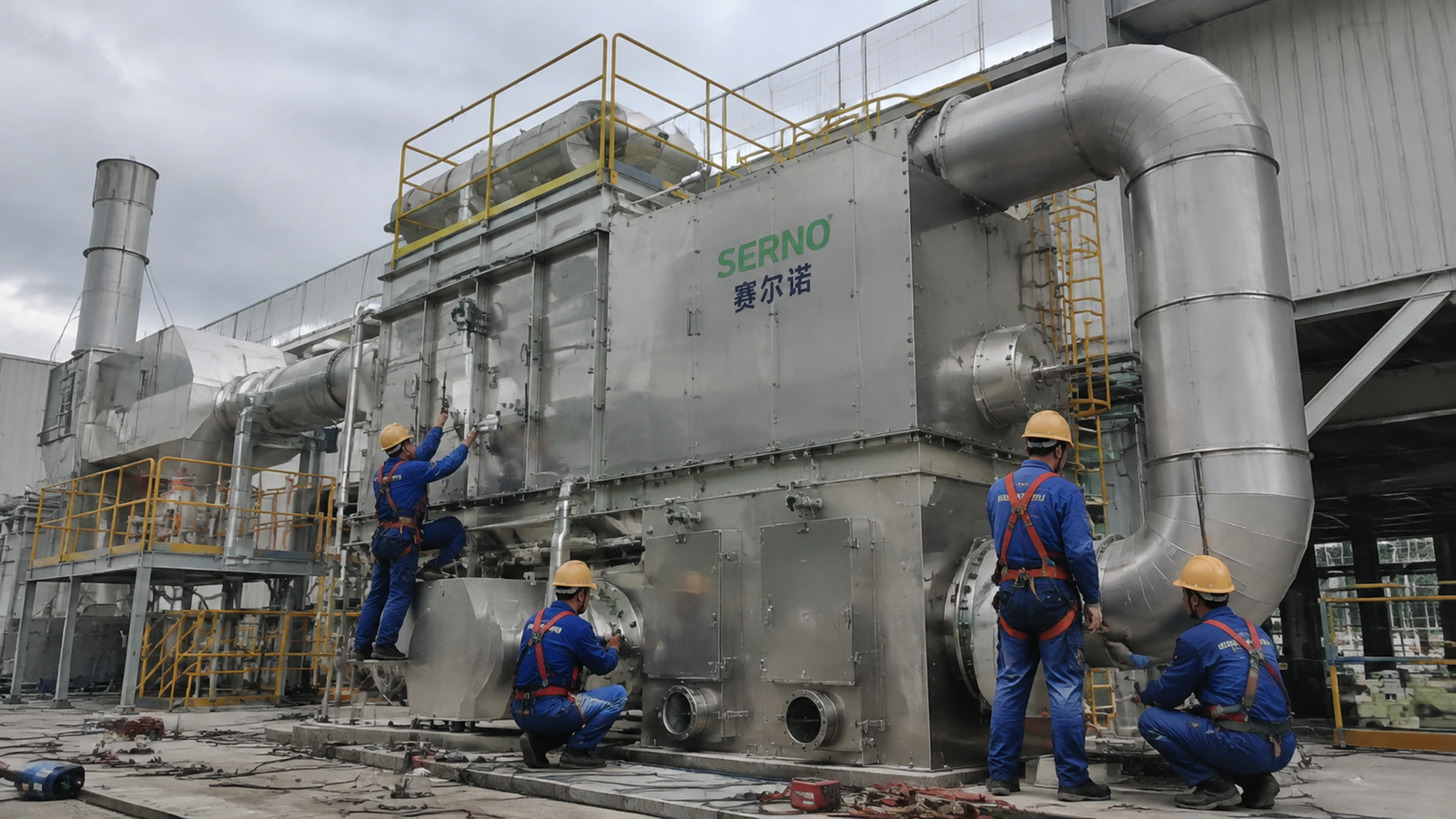
During a properly isolated, cooled outage, inspect inlet transitions, turning vanes, perforated plates, media retainers and accessible plenum areas against the as-built drawing. Look for debris, loose components, blocked openings, distorted plates and unintended gaps. Photograph positions and dimensions. Never enter equipment or open an access point without the site’s confined-space, isolation and cooldown controls.
5. Test a hypothesis, not just a symptom
State the suspected mechanism and a measurement that could disprove it. For example, a partially closing valve should produce a repeatable phase-specific pressure signature; an upstream branch imbalance may persist across valve phases. Use controlled tests only under approved operating conditions. Avoid changing several dampers or control settings at once, because the effect of each change then becomes untraceable.
6. Build the evidence matrix
| Observation | Check first | Evidence for the work scope |
|---|---|---|
| One phase has repeatable high differential pressure | valve travel, taps, bed obstruction | aligned trends and valve inspection record |
| Uneven temperature across chambers | sensor locations, load, phase timing | calibrated trends at comparable load |
| Outlet result varies after switching | sample delay, purge path, valve sealing | synchronized sample and valve timeline |
| Local plenum anomaly | debris, plate damage, unintended gap | marked-up drawing and measured photographs |
| Fan operating point shifts | filter/duct resistance and fan control | flow and pressure baseline at known conditions |
7. Convert findings into a procurement-ready scope
Specify the affected chamber and operating case, inspection access, measurements, drawing revisions, isolation requirements and acceptance method. Ask bidders to separate instrument correction, valve repair, cleaning and engineered distribution modifications. Do not prescribe a plate opening pattern, pressure-drop limit or efficiency guarantee without the original design basis and site data. If hot spots or lining distress are also present, assess them through a separate refractory inspection before restart.
FAQ
Does an uneven chamber temperature prove maldistribution?
No. It is a useful lead, but sensor placement, load variation, heat storage and switching phase must be checked before attributing it to flow.
Can pressure drop alone identify a blocked media bed?
No. Confirm tap condition, valve position, flow and other resistance sources first. Compare measurements under equivalent operating cases.
What should a buyer request before ordering distribution hardware?
Request as-built drawings, phase-aligned trends, calibrated measurements, outage photographs, the proposed hydraulic/thermal basis and a measurable post-work verification plan.
Conclusion and CTA
Good RTO gas-distribution work begins with synchronized evidence and a falsifiable diagnosis. SERNO can review your flow path, operating trends and inspection scope to help define the next engineering step for an industrial VOC treatment project. Contact SERNO with the as-built layout and representative operating records for a technical discussion.