 Request Proposal
RTO Bypass Damper Inspection: Verify Safe Diversion Before a Trip
An RTO emergency bypass can protect a production line or exhaust system during defined abnormal conditions, but only if the complete diversion function works. A damper that moves during a workshop test may still fail under process pressure, leak in normal operation, discharge to an unsafe location or receive the wrong command during a real trip.
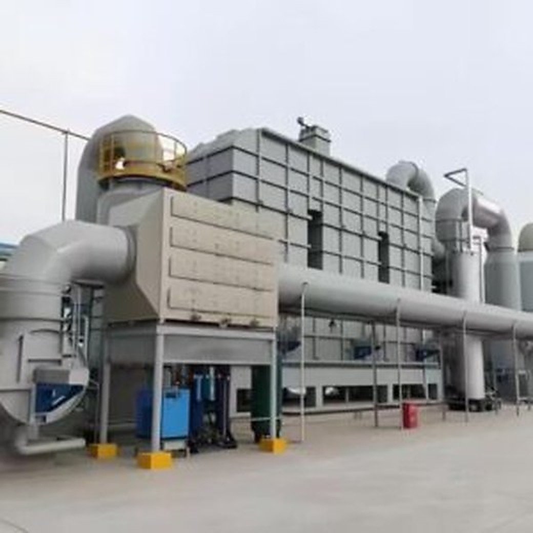
The inspection boundary therefore extends beyond the damper blade. It includes the actuator, position feedback, power source, control sequence, duct supports, weather protection, discharge point and the operating rules that determine when bypass is permitted. Environmental and safety requirements vary by jurisdiction and permit, so the acceptable use of bypass must come from the site authorization and approved cause-and-effect documentation.
Define the approved bypass function first
Start with the current process description, permit conditions, hazard review and cause-and-effect matrix. Identify every condition that may command the bypass, the intended fail position, the required response of production equipment and the operator actions that follow. Do not assume that all RTO trips should automatically divert untreated exhaust; some sites require production isolation or a different controlled response.
Confirm the design basis for maximum airflow, temperature, pressure and expected duration. Record whether the bypass serves equipment protection, personnel safety, process stability or a combination of these purposes. A clear functional statement prevents a mechanical test from being mistaken for proof of legal or operational acceptability.
Inspect the damper and duct boundary
With the system safely isolated under the site’s procedures, inspect the blade, shaft, bearings, seals, stops and casing. Look for corrosion, deposits, distortion, loose hardware, rubbing, heat damage and signs that the blade does not reach its mechanical end position. Check access doors and nearby duct joints for leakage evidence.
Inspect the surrounding duct supports and flexible connections. A damper can bind when thermal movement, settlement or duct load shifts the casing. Verify that drains, weather hoods and rain protection cannot introduce liquid or debris into the mechanism. Photograph reference marks at both commanded positions so later movement can be compared.
Prove actuator power and fail-state behavior
Record the actuator type, available torque or thrust basis, stroke time, power source and local override arrangement. Inspect air supply quality and reserve capacity for pneumatic units; inspect cable condition, overload protection and emergency supply for electric units. Confirm that the actuator is securely coupled to the shaft and that the linkage does not over-center or run out of travel.
Test loss-of-power behavior only through an approved procedure. The observed fail position must match the hazard review and control narrative. If stored energy, spring return or accumulator pressure is required, verify its condition and monitoring rather than relying on the nameplate alone.
Verify position feedback and control logic
Command the damper from each authorized control location and compare the physical blade position with local indicators, limit switches, HMI status and historian events. A green “open” indication is not sufficient if it comes from the command bit instead of independent position feedback.
Review permissives, time delays, alarm priorities and conflicting commands. Confirm how the RTO isolation damper, process exhaust fan, production line and bypass damper are sequenced to avoid deadheading, reverse flow or simultaneous unsafe paths. Any forced signal or temporary logic change used for testing should be controlled, recorded and removed before release.
Inspect the full discharge path
Walk the complete bypass route from the branch connection to the discharge point. Check for closed manual dampers, temporary blanks, construction debris, damaged expansion joints, inadequate supports and unauthorized connections. Verify that the outlet remains clear of air intakes, occupied work areas and ignition sources according to the approved site design.
Where monitoring, sampling or event recording is required, confirm that the relevant instruments and clocks are available and synchronized. Do not infer compliance from a successful airflow test; discharge authorization, reporting obligations and maximum bypass duration must be checked against current site requirements.
Run a controlled functional test
A controlled test should use an approved sequence, defined starting conditions and responsible observers. Record command time, initial movement, full-position feedback, associated damper and fan responses, alarms, production response and restoration to normal service. Where a live-flow test is permitted, compare actual pressure and airflow response with the design basis.
Stop the test if the system enters an unreviewed condition. Afterward, inspect for linkage movement, abnormal noise, casing distortion or leakage. Reconcile physical observations with the event log; unexplained timing or indication differences should be resolved before the bypass is released.
Build a release record and maintenance trigger
The release package should connect the approved function to physical evidence. Retain marked-up drawings, cause-and-effect references, inspection photographs, actuator data, position checks, functional-test results, deviations and signed dispositions. Record the next inspection trigger based on site procedure, operating history and environmental exposure.
Avoid treating a calendar test as permanent proof. Corrosion, dust loading, freeze conditions, control changes and duct modifications can change the function between scheduled inspections. Add reinspection triggers after actuator work, logic changes, duct repairs, abnormal trips or long periods without movement.
RTO bypass damper verification matrix
| Verification area | Evidence to collect | Release question |
|---|---|---|
| Approved function | Permit basis, hazard review, cause-and-effect | Is bypass allowed for this exact initiating condition? |
| Mechanical boundary | Blade, shaft, seals, stops, casing photos | Does the blade reach both positions without binding? |
| Actuator and utilities | Power source, air pressure, stored energy, stroke time | Will it move under the defined failure condition? |
| Position feedback | Local mark, independent switches, HMI and event log | Does every indication match physical position? |
| Sequence | Fan, isolation damper, production and alarm response | Does the system avoid blocked or conflicting flow paths? |
| Discharge route | Duct walkdown, outlet condition, monitoring readiness | Is the complete route clear and approved for use? |
| Close-out | Test record, deviations, restoration and sign-off | Is normal operation restored with no temporary overrides? |
FAQ
Is stroking the bypass damper with the process stopped enough?
No. It confirms only part of the function. The test also needs to address feedback, sequencing, utilities, the discharge path and the approved response to the initiating condition.
Should an RTO bypass damper fail open or fail closed?
There is no universal answer. The required fail position depends on the process hazard, exhaust-system design, permit conditions and approved cause-and-effect analysis.
Can HMI status prove that the damper is open?
Only when the status comes from verified independent position feedback and agrees with the physical position. A displayed command bit does not prove blade movement.
When should the bypass function be retested?
Follow the approved site interval and add event-based tests after actuator work, control-logic changes, duct modifications, abnormal trips or conditions that may cause corrosion, deposits or freezing.
Professional CTA
SERNO can review RTO bypass-damper scope, cause-and-effect interfaces and functional-test evidence against the actual process and project requirements. Share the exhaust flow range, operating temperature, damper arrangement, trip philosophy and applicable site constraints for a project-specific technical review.