 Request Proposal
RTO Alarm Rationalization: Build a Trip-Response Matrix Operators Can Use
An RTO can have hundreds of configured signals and still give operators too little useful guidance during a real upset. A high-high temperature alarm, a fan permissive failure and a valve-position mismatch may arrive within seconds of one another. If every event looks equally urgent, the control room sees noise rather than a sequence of cause and effect.
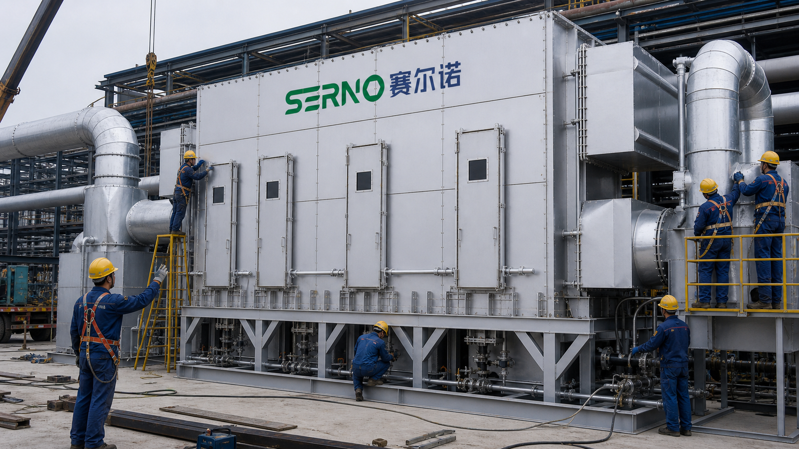
RTO alarm rationalization is the disciplined process of deciding which abnormal conditions deserve an alarm, how each alarm should be prioritized, what automatic action follows and what the operator must do next. The goal is not to suppress inconvenient messages. It is to make every alarm actionable, traceable and consistent with the equipment’s operating philosophy.
This guide shows how industrial buyers and plant teams can build a useful trip-response matrix without confusing alarms, permissives and protective trips.
Start with operating modes, not the PLC tag list
A raw tag export is a poor starting point because the same signal can mean different things during purge, heat-up, production, standby and shutdown. Map the normal sequence first. For each mode, identify which equipment is expected to run, which valves should be in position, which temperature and pressure signals are credible, and which transitions are time limited.
This prevents nuisance alarms that are predictable during a normal transition. A low combustion-chamber temperature may be abnormal in production but expected early in heat-up. A process-fan stopped indication may be a trip consequence, not the initiating cause. Mode context belongs in the alarm definition.
Separate alarms, permissives, interlocks and trips
These terms should not be used interchangeably.
- An alarm tells the operator that an abnormal condition requires awareness or action.
- A permissive is a condition that must be satisfied before a command or sequence can start.
- An interlock automatically changes or blocks equipment operation when defined logic is true.
- A trip moves the system toward a safer state after a protective limit or logic condition is reached.
One event may involve all four layers, but the documentation should show their relationship. For example, loss of combustion airflow can create an operator alarm, remove a burner permissive and initiate a burner trip. Listing three messages without the cause-and-effect chain makes troubleshooting slower.
Define each alarm with evidence and a response
Every retained alarm should have a documented purpose. At minimum, record the tag and plain-language message, operating modes in which it is active, setpoint basis, delay or debounce, priority, likely causes, automatic system action, required operator response, reset condition and restart authority.
The setpoint basis matters. It may come from equipment protection, process stability, burner-management logic, instrument range or a site operating limit. The matrix should identify the basis without inventing a universal value. Appropriate limits depend on the installed design, fuel system, VOC stream, applicable rules and the site’s approved safety review.
Use priority to represent consequence and response time
Priority is not a measure of how often an alarm occurs. It should reflect consequence severity and how quickly an operator must act. A practical workshop asks two questions: What happens if nobody responds, and how much time is available?
High-priority alarms should be rare and tied to defined immediate action. Medium-priority alarms normally require prompt diagnosis or intervention. Low-priority alarms can indicate developing conditions that should be addressed during routine operation. Notifications that require no operator action should usually be events or status messages rather than alarms.
Do not assign high priority simply to force attention. Too many high-priority alarms remove the distinction operators need during an upset.
Build the trip-response matrix
The matrix should let an operator understand the first-out cause, system action and safe next step without reading PLC code.
| Condition | Evidence to verify | Typical automatic action | Operator response | Restart boundary |
|---|---|---|---|---|
| Process fan airflow low | Fan status, VFD speed, differential pressure, damper position | Hold or trip affected sequence according to approved logic | Confirm airflow path; inspect fan, filter and damper evidence | Airflow proven and cause cleared |
| Burner flame failure | Flame signal trend, fuel-valve feedback, combustion-air status | Close safety shutoff valves; initiate approved purge logic | Do not repeatedly reset; inspect flame detection and fuel/air evidence | Burner-management conditions satisfied |
| Chamber temperature high-high | Independent temperature channels, rate of rise, VOC load trend | Remove heat input and move system toward designed protective state | Identify whether process load, valve leakage or instrument error initiated event | Temperature stable; initiating cause documented |
| Valve position mismatch | Command, open/closed feedback, actuator air/power, travel time | Block transition or trip if the valve is safety critical | Inspect actuator, linkage, limit switches and obstruction | Required position is positively proven |
| LEL signal high | Analyzer health, sample flow, calibration state, process source | Execute site-approved dilution, diversion or shutdown logic | Follow the approved site response; verify analyzer validity | Concentration boundary and analyzer health restored |
The entries above are generic engineering examples, not universal setpoints or sequence instructions. The final matrix must match the approved cause-and-effect document and site safety review.
Control alarm floods and identify the first-out event
During a trip, dozens of downstream alarms may follow one initiating fault. The historian should preserve the sequence of events at adequate time resolution, and the interface should identify the first-out condition where the control architecture supports it.
Review alarm floods by counting alarms in the minutes before and after a shutdown. Group consequential alarms under their initiating condition, apply mode-based suppression only where the logic is validated, and use delays only when a delay cannot hide a real hazard or equipment-protection need.
Shelving should be controlled, time limited and auditable. A standing instruction to ignore a recurring alarm is evidence that the alarm or the underlying equipment problem has not been resolved.
Validate the matrix during commissioning and after change
Desktop review is not enough. Test representative alarm paths using approved commissioning procedures. Confirm the field signal, PLC state, HMI message, priority, audible indication, historian record, automatic action and reset behavior. Record who witnessed the test and which revision of the logic was used.
Repeat relevant validation after instrument replacement, PLC or HMI modification, burner-service work, fan or damper changes, process expansion, recurring trips or a management-of-change action. A matrix that no longer matches the live logic is worse than no matrix because it creates false confidence.
What buyers should include in an RTO controls scope
For a new system or retrofit, request deliverables that make operation supportable after handover:
- Cause-and-effect matrix with revision control.
- Alarm list with priority, mode, delay, setpoint basis and operator response.
- First-out and sequence-of-events requirements.
- HMI alarm help text and naming conventions.
- Commissioning test records for critical alarms and trips.
- Backup and restoration procedure for PLC and HMI applications.
- Defined responsibility for site integration, remote signals and process shutdowns.
- Training that uses credible upset scenarios rather than screen navigation alone.
These items allow technical comparison between proposals. A long tag list does not show whether an alarm system will be usable under pressure.
FAQ
Should every PLC diagnostic create an operator alarm?
No. A diagnostic should become an alarm only when an operator must know about it and has a defined response. Other diagnostics may belong in maintenance views, event logs or condition-monitoring reports.
Can nuisance alarms simply be delayed?
Sometimes a validated delay is appropriate for signal chatter or a known process transient. But delay should not conceal poor instrumentation, unstable control, sticking hardware or an unsafe condition. Diagnose the cause before changing alarm timing.
Who should approve alarm priorities?
Use a cross-functional review involving operations, controls, process engineering, maintenance and EHS. Protective functions and burner-management logic also require the appropriate qualified specialists and the site’s formal change-control process.
What is the most useful record after an RTO trip?
A synchronized first-out event, sequence-of-events log and trend set covering the initiating signal, related commands, feedbacks, temperatures, pressures, airflow and process load. The exact channels depend on the installed system.
Turn alarm data into an operating tool
Alarm rationalization is complete only when operators can recognize the initiating condition, understand the automatic response and know the evidence required before restart. SERNO can review RTO operating modes, cause-and-effect documentation and controls scope with your engineering team. Share the existing alarm list, process sequence and recurring trip symptoms to begin a focused technical review.