 Request Proposal
Rotor RTO Seal Leakage Diagnosis: Prove Carryover Before Replacing Media
Unexpected VOC carryover from a rotor concentrator does not automatically mean the zeolite media has failed. Untreated air can cross a worn peripheral seal, move between process and regeneration sectors through a radial seal, or bypass the rotor through a distorted casing interface. The resulting outlet trend may look similar to lost adsorption capacity, yet the corrective work is completely different.
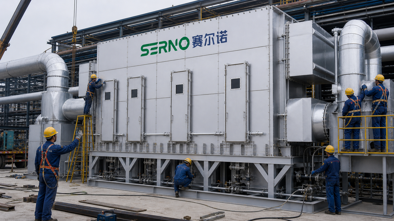
A disciplined rotor RTO seal leakage diagnosis treats the rotor, seals, sector pressures, drive and sampling system as one operating boundary. The objective is to prove where gas can move before changing rotor speed, increasing desorption temperature or ordering replacement media.
Define the symptom and operating case
Start with a repeatable operating case. Record production source, inlet VOC composition where known, inlet concentration trend, total airflow, process and desorption temperatures, humidity or condensation risk, rotor speed, fan frequencies, damper positions and the time since startup or a process change. Note whether the symptom is continuous, periodic with rotor rotation, limited to high load, or strongest during warm-up.
Confirm that inlet and outlet samples represent the same process interval. A long analyzer transport delay or samples taken across changing production can create an apparent removal problem. Review calibration and sample-line condition before using one number to condemn the rotor or its seals.
Understand the leakage paths
Peripheral seals control flow around the rotor circumference. Radial seals separate adjacent sectors across the rotor face. Axial or face-clearance errors can reduce contact or create local gaps, while a casing distortion or debris track can hold a seal open. The purge sector and its pressure relationship may also allow concentrated gas to enter the treated-air path if flow direction is wrong.
Leakage depends on both physical clearance and differential pressure. A small gap can become important when the pressure boundary drives untreated or concentrated gas toward the clean sector. That is why a visual seal check without pressure data is incomplete.
Build an evidence matrix before shutdown
Use stable trends to decide where the inspection should focus. The following matrix does not replace the equipment manual or site safety procedure; it organizes the evidence needed for a controlled diagnosis.
| Observation | Possible seal-related cause | Competing explanation | Useful check |
|---|---|---|---|
| VOC carryover changes with rotor position | Local radial or peripheral gap | Media contamination in one segment | Correlate outlet trend with indexed rotor position |
| Carryover rises after fan or damper change | Pressure-driven cross-leakage | Changed inlet loading | Compare sector pressures and inlet mass loading |
| Performance worsens as equipment warms | Thermal growth changes face clearance | Analyzer drift or desorption instability | Compare cold and stable-hot clearance evidence |
| Rub marks or dust tracks appear at one arc | Misalignment, runout or seal loading | Loose debris from upstream | Measure runout and inspect the complete track |
| Clean-sector VOC rises with purge upset | Incorrect purge pressure or seal path | Process concentration step | Verify purge airflow direction and pressure |
Do not interpret a single temperature or VOC reading in isolation. A strong diagnosis connects mechanical evidence with a reproducible operating change.
Inspect seals, rotor position and drive condition
After the rotor is isolated, cooled and released under the site’s lockout and confined-space rules, inspect the full circumference and each sector boundary. Record seal continuity, compression or clearance, fasteners, spring elements, joints, overlap direction, deposits, tears, hardening and heat damage. Photograph rub marks and dust tracks with an indexed rotor position so they can be compared after rotation.
Check rotor axial position, radial runout, bearing condition, support-wheel contact, shaft or hub condition and drive-chain or belt tracking as applicable. A new seal will not remain effective if the rotor is misaligned or the support system allows excessive movement. Rotate only by the approved maintenance method and confirm that clearances remain acceptable through a complete revolution.
Verify sector pressure and purge direction
Map pressures at comparable operating conditions on each side of the rotor and across process, purge and desorption sectors. Confirm the tap locations and instrument ranges; a blocked pressure tap can send the investigation in the wrong direction. The desired pressure hierarchy depends on the system design, so use the supplier’s approved basis rather than a generic target value.
Where the control system permits, make only one bounded change at a time and observe whether carryover responds in the predicted direction. Avoid using large fan or damper changes as a diagnostic shortcut: they may disturb capture at the production source or move the system outside its thermal and safety limits.
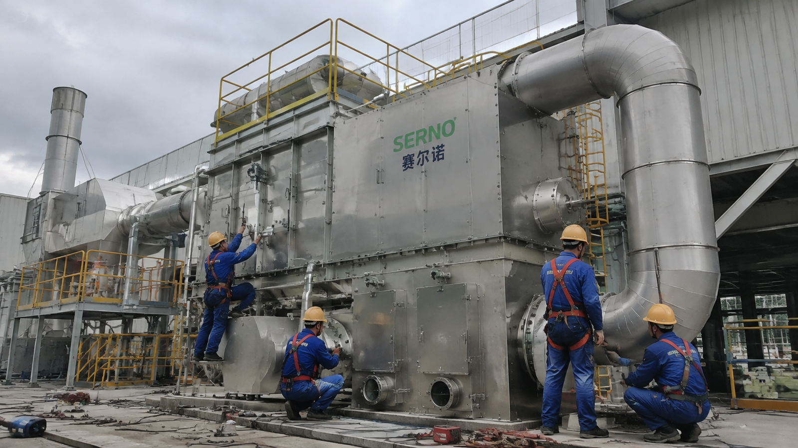
Separate seal leakage from media and desorption problems
Media condition should be evaluated after bypass paths and measurement errors are addressed. Review inlet contaminants, particulate or aerosol loading, humidity, adsorption temperature, desorption temperature profile and residence time. A uniformly degraded response may support a media or regeneration hypothesis; a position-linked or pressure-sensitive response more strongly supports a mechanical path, but neither conclusion should rest on trend shape alone.
If a controlled tracer or traverse test is considered, define the test material, injection point, detection method, process compatibility and safety approval in advance. Do not introduce an unapproved substance into a VOC system. Preserve baseline and post-adjustment data so the result is attributable.
Define repair and procurement acceptance evidence
A repair scope should state the seal material and profile, attachment method, allowable cold and hot clearances, rotor runout limit, adjustment method, access requirements and responsibility for correcting support or casing defects. Ask whether replacement seals are compatible with the actual temperature and contaminant exposure, not merely dimensionally similar.
Before release, require an inspection record, indexed clearance measurements, fastener and adjustment checks, clean rotation evidence, restored guards, pressure-map comparison and a controlled operating verification. Agree in advance how inlet/outlet sampling, production stability and analyzer timing will be handled. This prevents an ambiguous post-repair result from becoming a dispute over media, seals or process conditions.
FAQ
Does high outlet VOC prove that the zeolite rotor media is exhausted?
No. Seal bypass, sector pressure imbalance, incorrect purge flow, sampling delay, desorption instability and changing inlet load can produce similar symptoms. Verify these boundaries before concluding that the media requires replacement.
Can rotor RTO seal leakage be found by visual inspection alone?
Visual evidence is useful but incomplete. Seal gaps become significant through the pressure driving force, and some defects appear only at certain rotor positions or hot operating clearances. Combine inspection with pressure, rotation and VOC evidence.
Should rotor speed be increased to compensate for carryover?
Not until the cause is understood. A speed change affects adsorption and desorption residence time and can mask or worsen another problem. Use only approved operating limits and change one variable at a time.
What should a seal replacement quotation include?
It should define seal profile and material, quantities, access and labor boundaries, rotor alignment and runout checks, casing corrections, adjustment criteria, commissioning measurements, exclusions and acceptance evidence.
Conclusion
Rotor RTO seal leakage should be proved as a mechanical and pressure-boundary problem, not inferred from one outlet reading. A structured operating case, indexed inspection, pressure map and controlled verification help buyers distinguish a focused seal or alignment repair from unnecessary media replacement. SERNO can help review rotor concentrator inspection scopes, interface boundaries and acceptance evidence for new or upgraded VOC treatment systems.