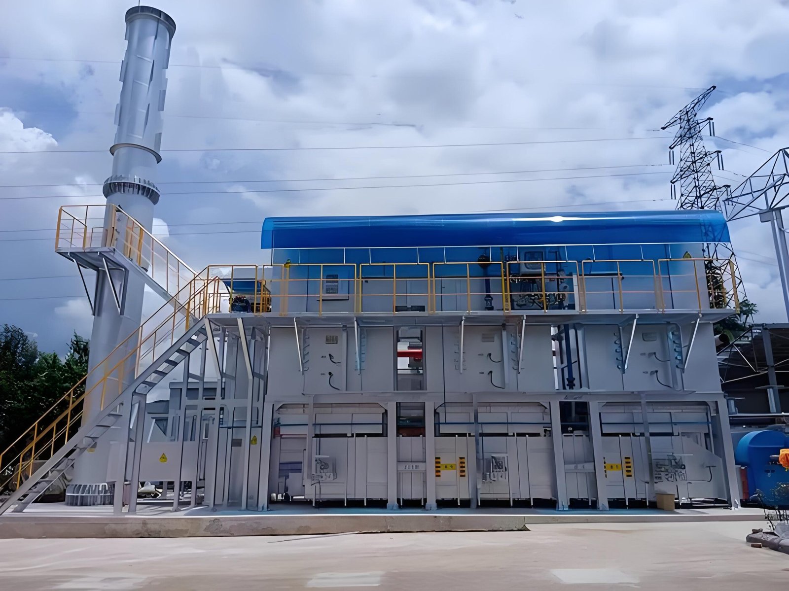
RTO Condensate Drain Inspection: Prevent Hidden Air Paths and Liquid Accumulation
Condensate drains are easy to overlook because they sit below the main exhaust path. Yet a blocked low point can retain liquid, while an open, dry, damaged, or incorrectly routed drain can become an unintended air path. Either condition may complicate pressure balance, corrosion review, startup, and troubleshooting.
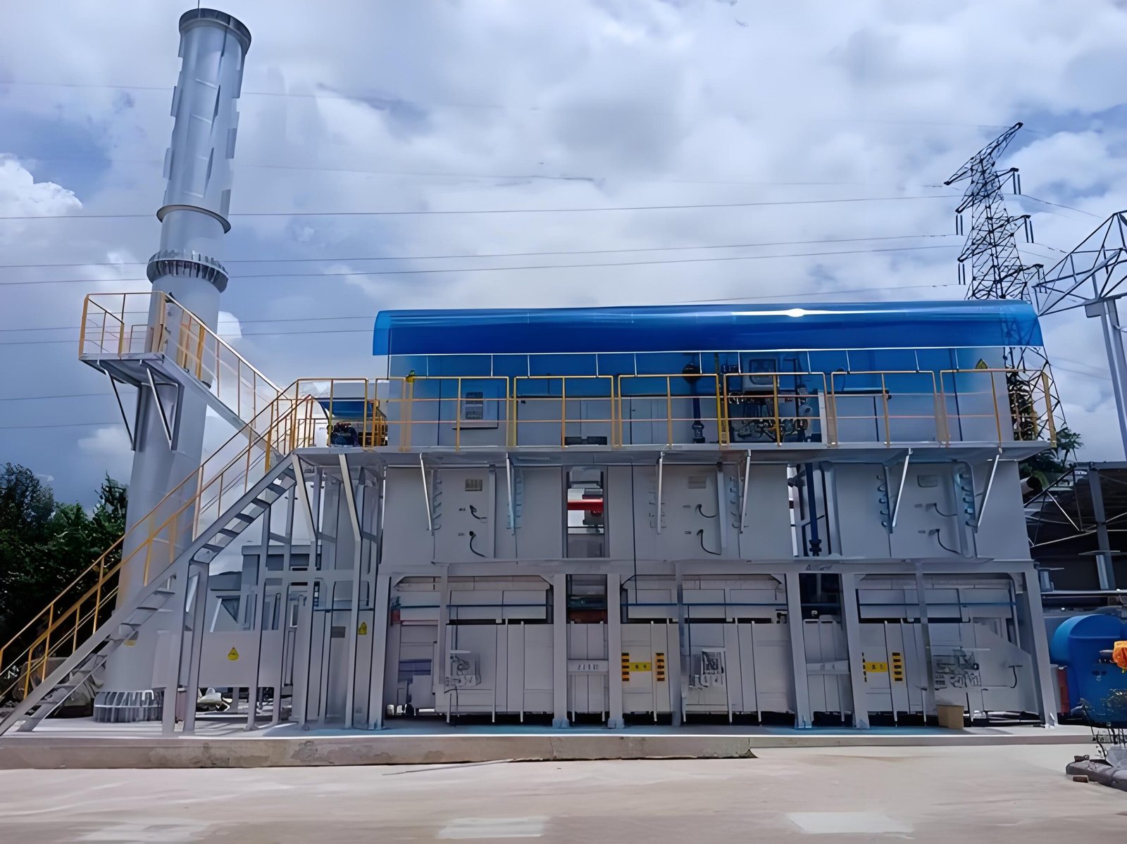
The correct question is not simply whether liquid comes out of a valve. Plant teams need to understand where liquid can form, how each drain maintains the gas boundary, what operating state was observed, and what evidence is required before return to service.
1. Map every low point and drain boundary
Start with current drawings and a field walkdown. Mark duct low points, knock-out sections, drain pots, traps, manual and automatic valves, hoses, heat tracing, insulation, discharge destinations, and nearby pressure connections. Confirm which sections operate under negative or positive pressure in startup, production, bypass, purge, and shutdown modes.
Do not assume that a drain shown on an old drawing still has the same routing. Record field differences for controlled review.
2. Identify credible liquid sources
Liquid may come from process carryover, condensation during cold startup, weather ingress, washdown, leaking coils, or an upstream separator upset. Document the production case, exhaust temperature, recent shutdown history, ambient conditions, and upstream changes. Avoid assigning the liquid to one source without evidence.
3. Inspect without opening an uncontrolled gas path
Follow site isolation, lockout, cooling, gas-testing, and PPE requirements. Check for corrosion, plugged tubing, damaged valves, missing caps, failed seals, frozen or inactive heat tracing, sagging hoses, unsupported piping, and discharge lines that rise after leaving the low point.
A drain should not be opened on a live boundary merely to prove flow. The safe verification method depends on the installed design and site procedure.
4. Separate blockage clues from false-air clues
| Observation | Possible explanations | Evidence to collect |
|---|---|---|
| Liquid remains at a low point | Plugging, poor slope, closed valve, failed tracing, or excess carryover | Level evidence, line condition, tracing status, operating history |
| Pressure changes near a drain | Dry trap, open valve, damaged seal, instrument drift, or another duct leak | Valve position, trap condition, pressure checks, comparable operating case |
| Corrosion around a drain | Condensation, chemical carryover, external water, or insulation damage | Liquid characterization, photos, material records, insulation inspection |
| Repeated freezing | Inadequate tracing, insulation damage, power loss, or unsuitable routing | Circuit status, ambient history, routing and insulation review |
5. Define an RFQ-ready corrective scope
A useful work scope identifies the drain tag, drawing revision, pressure and temperature basis, materials, isolation assumptions, access, disposal boundary, tracing and insulation interfaces, inspection hold points, and required as-left records. State whether the supplier must clean, repair, reroute, replace, or only inspect each component.
6. Establish restart release evidence
Before restart, confirm valve lineup, caps and plugs, trap fill or seal condition where applicable, tracing availability, insulation closure, discharge routing, and removal of temporary hoses or blanks. Record photographs and responsible sign-off. During controlled startup, watch pressure, temperature, fan load, drain condition, and any recurrence of liquid.
7. Build a repeatable inspection record
Keep the tag, location, operating state, observed liquid, valve position, tracing status, photographs, deviations, and action owner in one searchable record. Trend evidence is more useful than an isolated statement that a drain was “checked.”
Buyer checklist
- Are all low points and drains shown on current drawings?
- What maintains the gas seal in each operating mode?
- Who owns isolation, cleaning, waste handling, tracing, and insulation?
- Which measurements must be confirmed before fabrication?
- What inspection and restart records are included in the supplier scope?
FAQ
Can an open RTO drain affect system pressure?
It can if the drain communicates with a negative- or positive-pressure gas path, but the effect depends on the installed arrangement. Verify the boundary rather than assuming a universal result.
Does liquid at a drain prove process carryover?
No. Condensation, weather, washdown, and other sources must also be considered.
Should every drain have heat tracing?
Not universally. The decision depends on climate, liquid properties, routing, operating states, and the approved design basis.
What should be checked after drain work?
Confirm mechanical closure, valve lineup, seal condition, routing, tracing and insulation, then observe the controlled restart using defined pressure and temperature indicators.
Professional CTA
If your RTO has recurring liquid accumulation, frozen drains, corrosion at low points, or an unexplained pressure change, send SERNO the current duct layout, drain photographs, operating states, and recent maintenance history. We can help organize the evidence and define a technically comparable inspection or repair scope.